


10
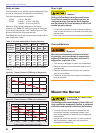
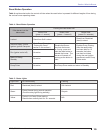
Set dimension Z
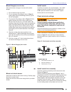
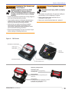
Loosen fastener c in Figure 7. Slide the nozzle line
and plate assembly until dimension Z in Figure 6 is:
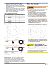
CF500 - 1-9/16” ±1/16”
CF800 - 1-3/4” ±1/16”
When dimension Z (from end of air tube to fl at area
of front face of head) is correctly set, tighten acorn
nut (item c).
Attach the oil line from the oil valve to the nozzle line
end. Tighten securely.
Before proceeding, check dimension Z once again.
Loosen acorn nut c if necessary to reposition the
nozzle line. Once dimension Z is set, do not loosen
the acorn nut (item) c again. Note that for the
setting of fastener d, refer to the initial head position
procedure under “Start-up Checklist” section (Pg.18).
Insert burner
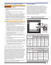
Position the burner in the front of the appliance and
loosely tighten the nuts on the mounting studs. The
burner should be pitched downward 2° as shown in
Figure 4.
Secure the burner to the appliance by tightening the
nuts on the burner fl ange mounting studs.
○
○
○
○
○
○
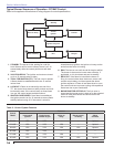
Figure 7 - Adjusting plate assy.
Legend (Figures 7)
c
Bottom acorn nut
d
Fastener
e
Indicator adjusting plate
f
Secondary adjusting plate
Figure 6 - Nozzle line assembly in burner
CF500
1-9/16”
CF800
1-3/4”
Section: Mount the Burner
Z-Dim.
Z
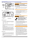
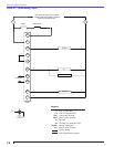
Fuel unit by-pass plug
The CF500 and CF800 burners are shipped without
the by-pass plug installed in the fuel line.
The by-pass plug must NOT be installed when using
with a one-pipe oil system.
The by-pass plug MUST be installed when using a
two-pipe oil system.
Oil supply/return lines
○
○
○
Do Not Install By-pass Plug
with 1-Pipe System
Failure to comply could cause immediate pump seal
failure, pressurized oil leakage and the potential for a
fi re and injury hazard.
The burner is shipped without the by-pass plug installed.
Intall the by-pass plug in two-pipe oil supply systems
ONLY.
y
y
Install Oil Supply To
Specifi cations
Failure to properly install the oil supply
system could cause oil leakage,
equipment malfunction, puff-back of
hot gases, heavy smoke, asphyxiation,
explosion and fi re hazards.
Carefully install the oil supply lines, fi ttings and
components using the guidelines provided in this section.
The oil supply must comply with the latest edition of NFPA
31 (Canada CSA B139) and all applicable codes.
Do NOT install valves in return lines.
If the oil supply inlet pressure to the pump exceeds 3 psig
or for gravity feed systems, install an oil safety or pressure
reducing valve (Webster OSV, Suntec PRV or equivalent).
y
y
y
y
Install the oil tank and oil lines in accordance with all
applicable state and local codes.
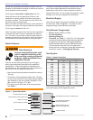
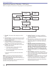
Size the oil supply and return lines using the
guidelines given in the fuel unit literature included in
the literature envelope. Oil line fl ow rate will equal
the burner rate for one-pipe systems. For two-pipe
systems, refer to Table 3 for the fuel unit gear set
capacity - the rate at which fuel is recirculated when
connected to a two-pipe system. However, size two-
pipe oil lines based on this fl ow rate.
Use continuous lengths of heavy-wall copper tubing,
routed under the fl oor where possible. Do not attach
fuel lines to the appliance or to fl oor joists if possible.
This will reduce vibration and noise transmission
problems.
○
○
○