


7
CF500/CF800 Burner Manual
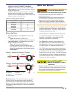
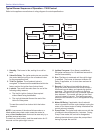
Verify Firing Rate
Refer to appliance manufacturer’s instructions (if
available) for fi ring rate and nozzle selection. Otherwise,
the maximum recommended fi ring rate for the burner
depends on the length of the fi ring chamber and the
distance from the burner center to the chamber fl oor.
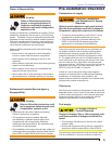
Verify that the chamber dimensions are at least as
large as the minimum values given in Figure 2. If the
appliance dimensions are smaller than recommended,
reduce the fi ring rate accordingly.
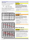
Starting with minimum gph fi ring rate, the minimum
size recommended is 8” fl ue pipe with 8” X 8”
inside chimney, unless specifi ed otherwise by the
appliance manufacturer.
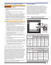
A chimney fl ue shall extend at least 3 feet above
the highest point at which the chimney comes in
contact with the roof, and not less than 2 feet above
the highest roof surface or structure within 10 feet
horizontally of the chimney. Refer to Figure 2.
Any accumulation of soot or debris in chimney
offsets should be removed
Any obstructions such as a protruding joint or a
piece of broken tile wedged in the chimney should
be removed.
No other appliance connection should be made to
the same fl ue pipe.
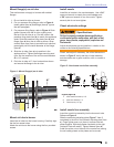
The fl ue pipe should have an upward pitch toward the
chimney of at least 1/4” per foot of length. It should fi t
tightly and should not project into the chimney.
Any leakage between tiles, around clean-out doors,
or around the vent pipe should be sealed.
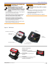
INSULATED STAINLESS STEEL CHIMNEY LINERS
The new designs of high effi ciency oil furnaces and
boilers in conjunction with fl ame retention oil burners are
more effi cient. One result of increased effi ciency is lower
fl ue gas temperatures. As fl ue gases rise in the chimney,
they will cool and condense when they reach the dew
point. The condensation will mix with the sulphur in the
fl ue gases creating sulphuric acid. The acid will attack the
chimney mortar, brick and clay liners causing corrosion,
deterioration and blockage of the chimney. Eventually
the blockage could prevent exhausting the fl ue gases.
Instead, the fl ue gases could vent out the barometric
damper into the living space.
Therefore, it is strongly recommended that an approved
insulated stainless steel liner be installed.
1.
2.
3.
4.
5.
6.
7.
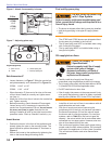
Fire, Smoke & Asphyxiation
Hazard
Carefully inspect the chimney or exhaust vent system.
Make sure it is properly sized and in good working
condition.
Follow the instructions supplied by the appliance
manufacturer.
The installation must strictly comply with all applicable
codes, authorities having jurisdiction and the latest
revision of the National Fire Protection Association
Standard NFPA 31 for the installation of chimneys and
vent sizing, (or CSA-B139 and CSA-B140 in Canada).
Regulation by these authorities take precedence over
the general instructions provided in this manual.
y
y
y
y
y
Inspect Chimney or Direct Vent System
Section: Pre-installation Checklist
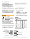
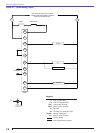
Firing Rate
Minimum Dimensions
(with damper) (without damper)
HLHL
1.75 to 3.00 gph
7.5” 18.0” 8.0” 19.0”
4.00 gph
8.0” 21.0” 9.5” 23.0”
5.00 gph
9.0” 23.0” 10.5” 30.0”
6.00 gph
10.0” 28.0” 11.5” 40.0”
7.00 gph
11.0” 34.0” 12.0” 46.0”
8.00 gph
14.0” 38.0” 14.0” 51.0”
Figure 2. - Dimensions: Minimum Combustion
Chamber and Air Tube Mounting.
* Install burner with
2° pitch as shown.
*2°
L
H
1/4”
T
Air Tube Length
(Dimension T)
A.T.C. Codes
(A.T.C. = Air Tube Combination)
CF500
CF800
Tube A Tube B
6.00”
CF 60 KK CF 60 KH CF 60 KJ
8.00”
CF 80 KK CF 80 KH CF 80 KJ
10.00”
CF 100 KK CF 100 KH CF 100 KJ
14.00”
CF 140 KK CF 140 KH CF 140 KJ
16.00”
CF160 KK -- --
17.00”
-- CF 170 KH CF 170 KJ