


Manual 2100-467K
Page 24 of 24
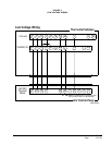
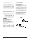
FIGURE 11
TROUBLESHOOTING GE X13-SERIES ECM2.3
™
MOTORS CONT’D.
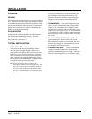
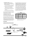
Model X13 Communication Diagnostics
The X13 motor is communicated through 24 VAC low voltage
(Thermostat Control Circuit Wiring).
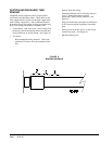
1. Start with unit wiring diagram to conrm proper
connections and voltage (see Figure 11).
2. Initiate a demand from the thermostat and check the
voltage between the common and the appropriate motor
terminal (1-5). (“G” input is typically on terminal #1, but refer
to wiring diagram!)
a. If the low voltage communication is not present, check
the demand from the thermostat. Also check the
output terminal and wire(s) from the terminal strip or
control relay(s) to the motor.
b. If the motor has proper high voltage as identied
above (Motor not Running #1), and proper low voltage
to a programmed terminal, and is not operating, the
motor is failed, and will require replacement.
Manual 2100-467H
Page 23 of 23
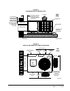
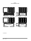
FIGURE 11
TROUBLESHOOTING GE X13-SERIES ECM2.3
™
MOTORS
CONT’D.
Model X13 Communication Diagnostics
The X13 motor is communicated through 24 VAC low voltage
(Thermostat Control Circuit Wiring).
1. Start with unit wiring diagram to confirm proper
connections and voltage (see Figure 11).
2. Initiate a demand from the thermostat and check the
voltage between the common and the appropriate motor
terminal (1-5). ("G" input is typically on terminal #1, but
refer to wiring diagram!)
a. If the low voltage communication is not present, check
the demand from the thermostat. Also check the
output terminal and wire(s) from the terminal strip or
control relay(s) to the motor.
b. If the motor has proper high voltage as identified
above (Motor not Running #1), and proper low voltage
to a programmed terminal, and is not operating, the
motor is failed, and will require replacement.
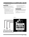
24VAC "R" Signal through
thermostat output.
24VAC Common
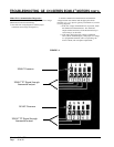
24VAC Common
24VAC "R" Signal through
thermostat output.