


Manual 2100-467K
Page 13 of 24
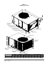
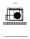
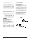
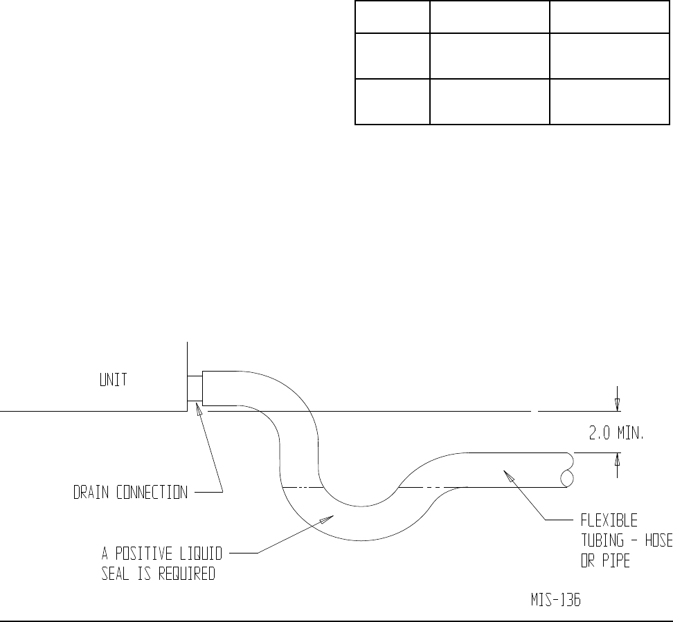
FIGURE 5
CONDENSATE DRAIN TRAP
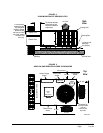
5. OTHER INSTALLATIONS – Many other
installations are possible with the packaged air
conditioner. No matter what the installation, always
consider the following facts:
A. Insure that the discharge air is not obstructed in
any way so as to cause operation difculties.
B. The indoor coil drain pan is equipped with a
coupling that must be piped through a
condensate drain trap to a suitable drain.
C. Always mount the unit is such a position that it
may be easily reached for servicing and
maintenance.
D. Insure that the unit is clear so that proper air
ow over the outdoor coil will be maintained.
If this unit is operated in cooling below a 55° outdoor
ambient temperature, the installation of low ambient
controls (CMA-28) to unit is required.
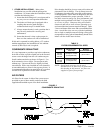
CONDENSATE DRAIN TRAP
It is very important to provide a trap in the condensate
drain line to allow a positive liquid seal in the line and
assure correct drainage from the coil condensate pan.
Install condensate drain trap shown in Figure 8. Use
drain connection size or larger. Do not operate unit
without trap. Unit must be level or slightly inclined
toward drain. With a trap installed on a unit located in
an unconditioned area, water in the trap may freeze. It
is recommended that the trap material be of a type that
will allow for expansion of water when it freezes.
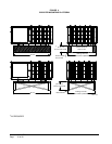
AIR FILTERS
Air lters for the return air side of the system are not
provided as part of these models, and must be eld
supplied and installed as part of the nal installation.
Prior thought should be given to return air location and
placement of the air lter(s). The air lter(s) must be
of adequate size and readily accessible to the operator
of the equipment. Filters must be adequate in size and
properly maintained for proper operation. If this is
not done, excessive energy use, poor performance, and
multiple service problems will result. It is impossible
to oversize air lters. Generous sizing will result in
cleaner air and coils as well as lower operating costs
and extend the time between required changes. Table
5 shows minimum lter areas and recommended lter
sizes. Actual lter sizes can vary with the installation
due to single or multiple returns utilizing a lter/grille
arrangement or being placed immediately ahead of the
indoor coil face in the return air duct.
NOTE: If roof hood accessory is to be used,
information on air lters may be found under
that heading in this manual. Air lters are
supplied as part of that package.
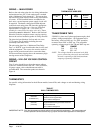
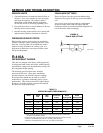
TABLE 5
FILTER REQUIREMENTS & SIZES
Model No.
Minimum Filter
Free Area
Minimum
Recommended Size
PA1324
PA1330
PA1336
403 Square Inches
(2.8 Square Feet)
(2) 14 x 20 x 1
PA1342
PA1348
PA1360
473 Square Inches
(3.3 Square Feet)
(2) 16 x 20 x 1