


Manual 2100-467K
Page 19 of 24
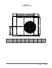
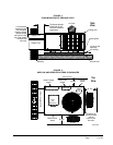
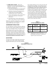
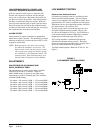
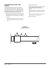
FAN BLADE SETTINGS
Shown in Figure 8 are the correct fan blade setting
dimensions for proper air delivery across the outdoor
coil.
Any service work requiring removal or adjustment
in the fan and/or motor area will require that the
dimensions below be checked and blade adjusted in or
out on the motor shaft accordingly.
MD-1417BC
SERVICE AND TROUBLESHOOTING
SERVICE HINTS
1. Caution homeowner to maintain clean air lters at
all times. Also, not to needlessly close off supply
and return air registers. This reduces airow
through the system which shortens equipment
service life as well as increasing operating costs.
2. Check all power fuses or circuit breakers to be sure
that they are the correct rating.
3. Periodic cleaning of the outdoor coil to permit full
and unrestricted airow circulation is essential.
PRESSURE SERVICE PORTS
High and low pressure service ports are installed on
all units so that the system operating pressures can be
observed. Pressure tables can be found later in this
manual covering all models on cooling cycle. It is
imperative to match the correct pressure table to the
unit by model number.
R-410A
REFRIGERANT CHARGE
This unit was charged at the factory with the quantity
of refrigerant listed on the serial plate. AHRI capacity
and efciency ratings were determined by testing with
this refrigerant charge quantity.
The following pressure tables show nominal
pressures for the units. Since many installation
specic situations can affect the pressure readings,
this information should only be used by certied
technicians as a guide for evaluating proper system
performance. They shall not be used to adjust charge.
If charge is in doubt, reclaim, evacuate and recharge
the unit to the serial plate charge.
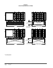
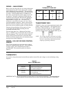
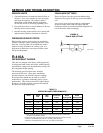
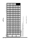
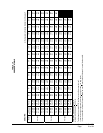
TABLE 8
INDOOR BLOWER PERFORMANCE
1 MotorwilldeliverconsistentCFMthroughvoltagesupplyrangewithnodeterioration
(197-253V for all 230/208V models).
2 Continuous CFM is the total air being circulated during continuous (manual fan) mode.
3 Will occur automatically with a call for “Y” for cooling mode operation.
4 Will occur automatically with a call for “W1” for heating mode operation.
FIGURE 8
FAN BLADE SETTING
Model
Rated
ESP
MAX
ESP
Continuous
Airow
Rated
Cooling CFM
m
Rated
Heating CFM
PA1324 0.10 0.50 600 800 800
PA1330 0.15 0.50 750 1000 1000
PA1336 0.15 0.50 825 1100 1100
PA1342 0.20 0.50 925 1400 1400
PA1348 0.20 0.50 1025 1550 1550
PA1360 0.20 0.50 1150 1750 1750
3¼"