


Manual 2100-467K
Page 2 of 24
CONTENTS
Getting Other Informations and Publications .........3
General Instructions
Important .................................................................4
Shipping Damage .....................................................4
General .................................................................4
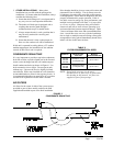
Field Installed Heater Packages (Optional) ..............4
Installation
Location ...............................................................10
Slab Mounting ......................................................... 10
Typical Installations ......................................... 10 & 13
Condensate Drain Trap ...........................................13
Air Filters ...............................................................13
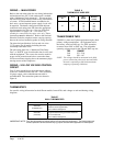
Wiring – Main Power ...............................................14
Wiring – 24V Low Voltage Control Circuit ...............14
Transformer Taps .................................................... 14
Thermostats ............................................................ 14
Start Up and Operation
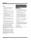
General ...............................................................16
Topping Off System Charge ....................................16
Safety Practices ...................................................... 16
Start Up Notes ........................................................16
Three Phase Scroll Compressor Start Up
Information .............................................................. 17
Sequence of Operation ........................................... 17
Indoor Blower Motor ................................................17
Compressor Control Module ...........................17 & 18
Adjustments ............................................................18
Low Ambient Control ...............................................18
Service and Troubleshooting
Service Hints ...........................................................19
Pressure Service Ports ...........................................19
R-410A Refrigerant Charge .................................... 19
Fan Blade Settings .................................................19
Pressure Tables ..............................................20 & 21
Suction and Discharge Tube Brazing ......................22
Troubleshooting GE Blower Motors .................23-24
Figures
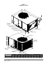
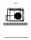
Figure 1A Unit Dimensions ....................................... 8
Figure 1B Unit Dimensions ....................................... 9
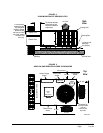
Figure 2 Slab Mounting at Ground Level .............. 11
Figure 3 Airow and Service Access
Clearances ............................................. 11
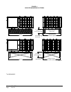
Figure 4 Elevated Mounting Platform ................... 12
Figure 5 Condensate Drain Trap ..........................13
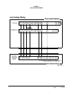
Figure 6 Low Voltage Wiring ................................15
Figure 7 Low Ambient Control Wiring ...................18
Figure 8 Fan Blade Setting ...................................19
Figure 9 Brazing Diagram ....................................22
Figure 10 Motor Connections ................................. 23
Figure 11 Wiring (Connections/Voltage) .................24
Tables
Table 1 Rated CFM & ESP ...................................4
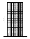
Table 2 Electrical Specications ...........................5
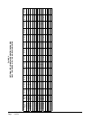
Table 3 Opt. Field Installed Heater Packages .......6
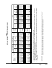
Table 4 Opt. Field Installed Elec. Heater ..............7
Table 5 Filter Requirements & Sizes ...................13
Table 6 Thermostat Wire Size .............................14
Table 7 Wall Thermostats ...................................14
Table 8 Indoor Blower Performance ...................19
Table 9 Pressure Table .......................................20
Table 10 Pressure Table .......................................21