


Manual 2100-467K
Page 14 of 24
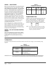
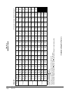
TABLE 6
THERMOSTAT WIRE SIZE
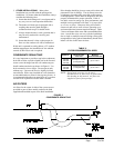
TRANSFORMER TAPS
230/208V, 1 phase and 3 phase equipment employ dual
primary voltage transformers. All equipment leaves
the factory wired on 240V tap. For 208V operation,
reconnect from 240V to 208V tap. The acceptable
operating voltage range for the 240 and 208V taps are:
TAP RANGE
240 253 – 216
208 220 – 187
NOTE: The voltage should be measured at the eld
power connection point in the unit and while
the unit is operating at full load (maximum
amperage operating condition).
WIRING – MAIN POWER
Refer to the unit rating plate for wire sizing information
and maximum fuse size. Each outdoor unit is marked
with a “Minimum Circuit Ampacity”. This means that
the eld wiring used must be sized to carry that amount
of current. If eld installed heaters are added to the
basic unit, a second separate power supply circuit will
be required. The heater rating plate located adjacent
to the basic unit rating plate will show the appropriate
circuit ampacity fuse size, etc. (Also see “Electrical
Specications” on pages 5 & 7.) All models are
suitable for connection with copper wire only. These
instructions must be adhered to. Refer to the National
Electrical Code for complete current carrying capacity
data on the various insulation grades of wiring material.
The electrical specications list fuse and wire sizes
(75°F copper) for all models including the most
commonly used heater sizes.
The unit rating plate lists a “Maximum Time Delay
Fuse” or “HACR” type circuit breaker that is to be used
with the equipment. The correct size must be used for
proper circuit protection and also to assure that there
will be no nuisance tripping due to the momentary high
starting current of the compressor.
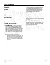
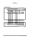
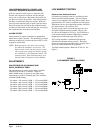
WIRING – 24V LOW VOLTAGE CONTROL
CIRCUIT
Five (5) wires should be run from thermostat subbase
to the 24V terminal board in the unit. A ve conductor,
18 gauge copper, color-coded thermostat cable is
recommended. The connection points are shown in
Figure 6.
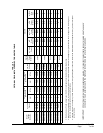
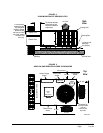
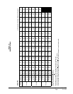
THERMOSTATS
See specic wiring information for the different models, heater KWs, and voltages on unit and heating wiring
diagrams.
IMPORTANT NOTE: Only the thermostats as shown above will work with this equipment. The thermostats and
correct operation can be assured only by proper selection and application of these parts.
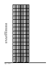
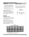
TABLE 7
WALL THERMOSTATS
Transformer
VA
FLA
Wire
Gauge
Maximum
Distance
In Feet
55 2.3
20
18
16
14
12
45
60
100
160
250
Thermostat Predominant Features
8403-058
(TH5220D1151)
2 stage Cool; 2 stage Heat
Electronic Non-Programmable
AutoorManualchangeover
8403-060
(1120-445)
3 stage Cool; 3 stage Heat
Programmable/Non-Programmable Electronic
HPorConventional
AutoorManualchangeover