


AXIS M1124–E Network Camera
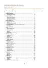
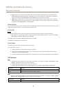
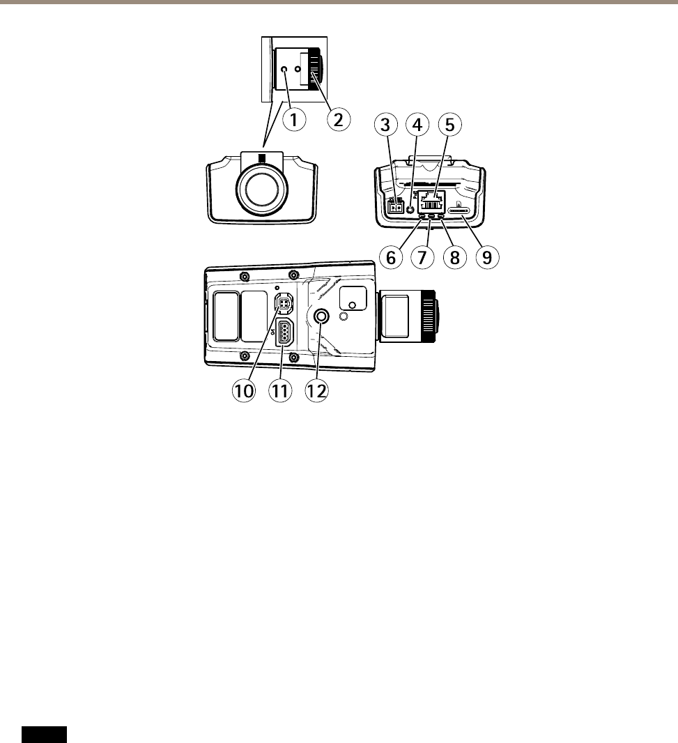
Hardware Overview
1
2
10
11
12
6
7
8
9
3
4
5
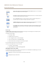
1
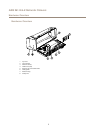
Zoom puller
2
Focus ring
3
Power connector
4
Control button
5
Network connector
6
Power LED
7
Status LED
8
Network LED
9
microSD card slot
10
Iris connector
11
I/O connector
12
¼
²
Screw mount
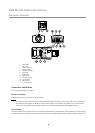
Connectors and Buttons
For technical specications, see page 61.
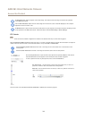
Network Connector
RJ45 Ethernet connector with Power over Ethernet (PoE).
NONO
NO
TICETICE
TICE
The product shall be connected using a shielded network cable (STP). All cables connecting the product to the network shall
be intended for their specic use. Make sure that the network devices are installed in accordance with the manufacturer’s
instructions. For information about regulatory requirements, see Electromagnetic Compatibility(EMC) on page 2 .
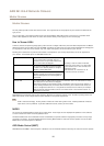
I/O Connector
Use with externaldevices in combination with,for example, tampering alarms, motiondetection, event triggering, time lapserecording
and alarm notications. In addition to the 0 V DC reference point and power (DC output), the I/O connector provides the interface to:
8