


AXIS M1124–E Network Camera
Technical Specifications
Built-in
installation
aids
Pixel counter
General
Casing
IP66- and NEMA 4X-rated, IK10 impact-resistant polymer enclosure
Color: White NCS S 1002-B
Memory 512 MB RAM, 256 MB Flash
Power
8-28 V DC or Power over Ethernet (PoE) IEEE 802.3af Class 2, max. 5.0 W, typical 3.6 W
Connectors
RJ45 10BASE-T/100BASE-TX PoE
Terminal block for one input and one output (12 V DC output, max. load 15 mA)
DC input, terminal block
Edge storage
Support for microSD/microSDHC/microSDXC card
Support for recording to dedicated network-attached storage (NAS)
For SD card and NAS recommendations see www.axis.com
Operating
conditions
–20 °C to 50 °C (–4 °F to 122 °F)
Humidity 10–100% RH (condensing)
Approvals
EN 55022 Class A, EN 61000-6-1, EN 61000-3-2, EN 61000-3-3, EN 61000-6-2, EN 55024, EN 50121-4,
FCC Part 15 Subpart B Class A, ICES-003 Class A, VCCI Class A, C-tick AS/NZS CISPR 22 Class A, KCC KN22 Class A,
KN24, EN 50581, IEC 60068-2-1, IEC 60068-2-2, IEC 60068-2-14, IEC 60068-2-30, IEC 60068-2-78
IEC/EN/UL 60950-22, IEC/EN 60529 IP66, NEMA 250 Type 4X, IEC/EN 62262 IK10, IEC 60721-4-4 Class 4M4
Dimensions
222 x 137 x 448 mm (8.7 x 5.4 x 17.6 in) including wall mount
Weight
1.6 kg (3.5 lb) including wall mount
Included
accessories
AXIS T94Q01A Wall Mount, Resistorx T20 tool, Connector kit, Installation Guide, Windows decoder 1-user license
Optional
accessories
AXIS T94R01P Conduit Back Box, AXIS T98A16-VE Surveillance Cabinet Series, AXIS T91A47 Pole Mount, AXIS
T90B Illuminators
Video
management
software
AXIS Camera Companion, AXIS Camera Station, Video management software from Axis’ Application Development
Partners available on www.axis.com/techsup/software
Warranty
Axis 1-year warranty and AXIS Extended Warranty option, see www.axis.com/warranty
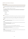
a. HorizontalAngle ofView
b. Vertical Angleof View
c. Thisproduct includessoftwaredevelopedbythe OpenSSLProject foruseintheOpenSSL Toolkit. (www.openssl.org),andcryptographic softwarewrittenby
Eric Young(eay@cryptsoft.com).
More information is available at www.axis.com
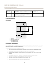
Connectors
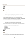
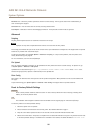
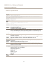
I/O Connector
4–pin terminal block
1
2 3 4
For an example diagram, see Connection Diagrams on page 63.
Function Pin Notes
Specications
0 V DC (-)
1
0 V DC
DC output
2
Can be used to power auxiliary equipment.
Note: This pin can only be used as power out.
12 V DC
Max load = 15 mA
62