


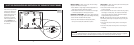
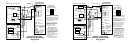
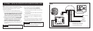

If installing this thermostat as part of a Model 6504 Intelligent Zoned Comfort System, refer to the Model 6504
Installation Manual for wiring and checkout procedures. Continue Model 6504 installation with Step 11 (page 36).
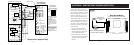
If wiring this thermostat directly to the HVAC equipment or standard zone control panel, continue with Step 5.
- 6 - - 7 -
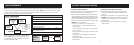
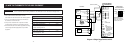
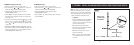
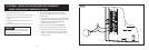
(4) SET THE CONFIGURATION DIP SWITCHES ON THE THERMOSTAT CIRCUIT BOARD
ON
O
HP
ELECT
SINGLE
B
HC
MULTI
GAS
STOP!
Figure 5
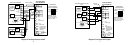
MULTI or SINGLE – When set to single, the second stage
outputs (Y2 and W2) do not energize.
• Set to SINGLE for single-stage furnace/AC applications or
single-stage compressor heat pump systems.
• Set to MULTI if the furnace or air conditioner is two-stage
or if the heat pump has a two-stage compressor.
HEAT/COOL or HEAT PUMP – When set to HP the compressor
terminal (Y1) is the first stage output for both heating and cooling.
• Set to HP when installed with heat pumps.
• Set to H/C when installed with furnace/AC systems,
roof top units or boiler/AC combination systems.
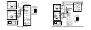
GAS or ELECT – When set to ELECT, the fan terminal (G) will
be energized on a call for heat.
• Set to ELECT when the heat source is electric
(such as strip heat).
• Set to GAS when the heat source is fossil fuel (oil, propane,
natural gas). For heat pumps, the compressor terminal(s)
will de-energize before the auxiliary heat terminal (W1) is
energized, thus acting as a fossil fuel kit.
O or B – For heat pumps only, this switch sets whether the
O/B reversing valve output is energized during a cooling call
or heating call.
• Set to O if heat pump reversing valve is to be energized
in cooling.
• Set to B if heat pump reversing valve is to be energized
in heating.
There are four dip switches
located on the back of the
thermostat (on the circuit
board) that must be set to
properly configure the
thermostat for operation
with the equipment it is to
control. Figure 5 shows
the default position for the
four switches.
90-1028