


IDS
ODT
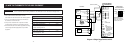
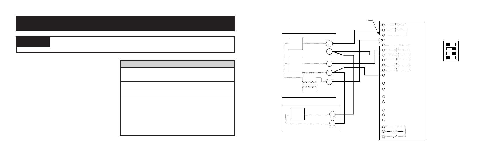
APRILAIRE MODEL
8570 THERMOSTAT
1ST
STG
COOL
AIR CONDITIONER
Y1
C
FAN
RELAY
1ST
STAGE
HEAT
R
FURNACE
C
G
Y1
W1
1ST STAGE
COOL
L1
L2
120
VAC
24
VAC
GND
ZA
ZB
I+
I-
6504
CONNECTION
B
O
Y2
Y1
G
RC
R
RH
W1
W2
C
AHC
CONNECTION
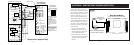
ELECT/GAS - SET TO
ELECT FOR ELECTRIC
HEAT, SET TO GAS FOR
FOSSIL FUEL HEAT
THERMOSTAT
CONFIGURATION
SWITCH SETTINGS
OUTDOOR (ODT)
& INDOOR (IDS)
TEMPERATURE
SENSORS
HC
SINGLE
B
GAS
HP
MULTI
O
ELECT
SUPPLIED JUMPER
4
3
2
1
ON
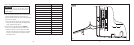
NC
NO
COM
EVENT
TRIGGERED
OUTPUT
(ETO)
- 8 - - 9 -
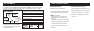
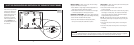
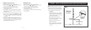
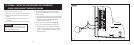
1. Run a cable with the correct number of wires
(see table) from the thermostat to the HVAC equipment.
2. Strip 1/4" of insulation from the end of the wires to
be connected to the thermostat.
3. Strip no more insulation than is required to make a
sound electrical connection at the HVAC equipment.
4. Wire the thermostat to the HVAC equipment according
to the wiring schematic appropriate for your HVAC
equipment.
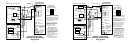
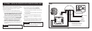
(5) WIRE THE THERMOSTAT TO THE HVAC EQUIPMENT
WARNING
120 volts may cause serious injury from electrical shock. Disconnect electrical power to the furnace
and air conditioner before starting installation. This thermostat is not a 120 volt (line voltage) device.
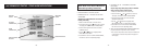
Application # Wires Diagram (Page)
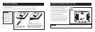
Single-Stage Furnace/AC 5 1 (9)
Two-Stage Furnace/AC 7 2 (10)
Two-Stage Roof Top Unit 7 3 (11)
Boiler w/AC (2-transformer) 6 4 (12)
Radiant 1st Stage Heat, 6 5 (13)
Furnace 2nd Stage and AC
Single-Stage Heat Pump 6 6 (14)
Single-Stage Heat Pump 7 7 (15)
w/Two Stages Aux. Heat
Two-Stage Heat Pump 8 8 (16)
Diagram 1: Single-Stage Furnace and AC