


- 2 - - 3 -
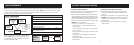
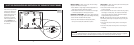
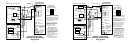
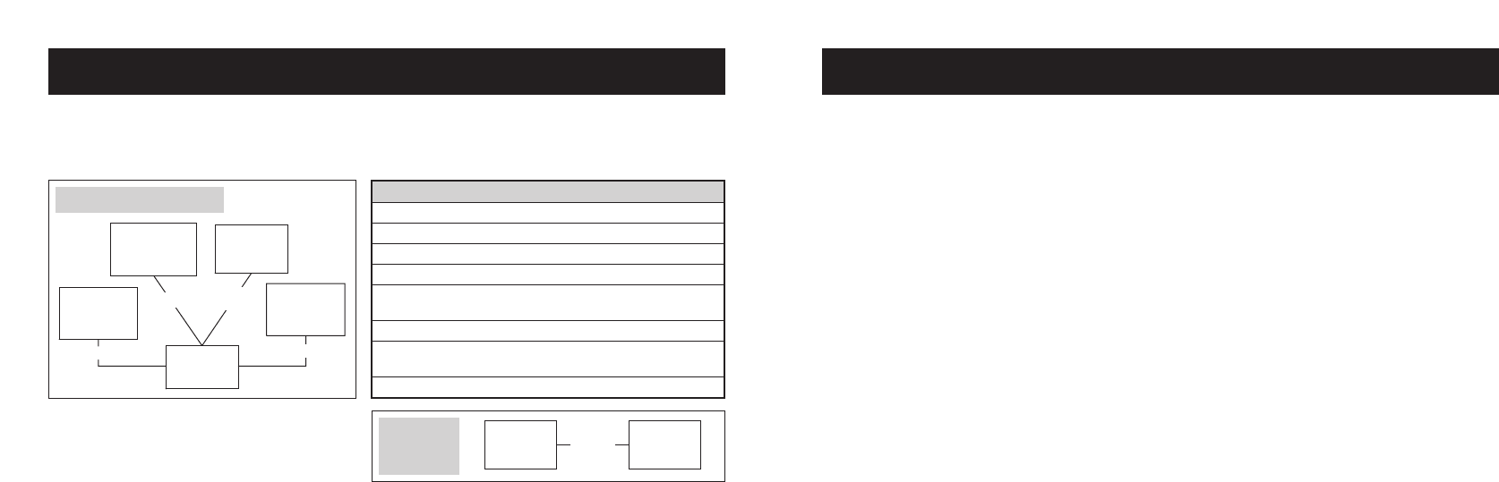
Figure 1 and the table show the number of wires that must be available at the thermostat in stand-alone thermostat systems
(i.e. not as part of an Aprilaire
®
Model 6504 Intelligent Zoned Comfort System). Figure 1 shows optional connections to both
an outdoor temperature sensor and an Aprilaire
®
Automatic Digital Humidifier Control (ADHC), but only one or the other is
necessary. All wire is standard 18-24 gauge thermostat cable.
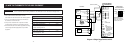
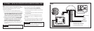
When this thermostat is connected to a Model 6504 as
shown in Figure 2, only one four-wire cable need be run
from the thermostat to the Model 6504. Use standard
18-24 gauge thermostat cable.
OPTIONAL –
AUTOMATIC
DIGITAL HUMIDIFIER
CONTROL
(ADHC)
HVAC
EQUIPMENT
MODEL 8570
THERMOSTAT
SEE
TABLE
2-WIRES
2-WIRES
2-WIRES
OPTIONAL –
OUTDOOR
TEMPERATURE
SENSOR
OPTIONAL –
INDOOR
TEMPERATURE
SENSOR
MODEL 8570
THERMOSTAT
MODEL 65044-WIRES
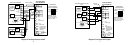
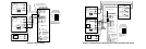
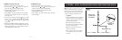
Application # Wires Diagram (Page)
Single-Stage Furnace/AC 5 1 (9)
Two-Stage Furnace/AC 7 2 (10)
Two-Stage Roof Top Unit 7 3 (11)
Boiler w/AC (2-transformer) 6 4 (12)
Radiant 1st Stage Heat, 6 5 (13)
Furnace 2nd Stage and AC
Single-Stage Heat Pump 6 6 (14)
Single-Stage Heat Pump 7 7 (15)
w/Two Stages Aux. Heat
Two-Stage Heat Pump 8 8 (16)
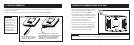
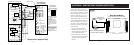
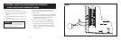
WIRE REQUIREMENTS (1) SELECT A MOUNTING LOCATION
If installing the thermostat alone…
• Mount on an interior wall, in a frequently occupied space.
• Keep the thermostat 18" from an outside wall.
• Mount the thermostat approximately 5 feet above the floor.
Height requirements are different for compliance with the
Americans with Disabilities Act (ADA) – 48" maximum height
for forward reach and 54" maximum height for side reach.
• Thermostat can be mounted to a vertical junction box (j-box).
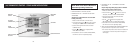
• DO NOT mount the thermostat:
– behind doors, in corners or other dead air spaces.
– in direct sunlight or near lamps, appliances or other
sources of heat.
– on an outside wall or wall exposed to an unconditioned
space (i.e. garage).
– in the flow path of a supply register, in stairways or near
outside doors.
– on a wall where concealed pipes or ductwork could
influence the sensor.
– near sources of electrical interference such as arcing
switch contacts.
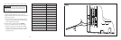
If installing an indoor temperature sensor…
• Mount the thermostat where it can be readily accessed.
Note that the backlighting illuminates whenever a button
is pressed.
• Thermostat can be mounted on a vertical junction box (j-box).
• DO NOT mount the thermostat where the operating range
temperatures will be exceeded (i.e. attic or unventilated
equipment room).
• Mount the sensor in the same location as if installing a
thermostat alone.
Figure 1 – Thermostat Wire
Figure 2 –
Model 6504
Wire