


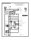
INTERNAL CONTROLLER
The internal controller within the humidifier cabinet responds to external inputs (e.g., humidistat and airflow proving switch) and
internal inputs (e.g., water level probe inside the steam chamber) to provide:
• Relative humidity (RH) control
– Model 1150: With an on-off demand signal, the controller
maintains RH within 5% to 7% of set point.
– Model 1160: With a modulating demand signal, the
humidifier maintains RH within 2% to 4% of set point.
Modulating demand signal options include a 0–10 VDC
humidistat signal (humidistat provided), or a signal by
others (0–10 VDC or 4–20 mA).
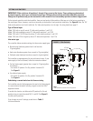
• Automatic water level control and safety shut-down
If there is insufficient water, an electronic water level
probe sends a signal to the controller to add water or to
turn off the heaters.
• Operating time monitoring
The controller accumulates humidifier run time to activate
end-of-season draining, water cool-down, and auto draining.
• Automatic preheating
During chamber refilling, once there is enough water in
the chamber, the heaters energizes at 100% until the
water approaches boiling temperature to preheat the
chamber water so it is warm when the humidifier receives
a humidity demand signal.
• Automatic end-of-season draining
If the humidifier doesn’t receive a humidity demand signal
for 72 hours, the chamber automatically drains.
• Periodic drain and flush
To reduce mineral buildup in the chamber, the humidifier
automatically drains at intervals based on operating time,
output capacity, and water type. At the end of the drain
cycle, the supply water is brought on to briefly flush the
chamber.
• Chamber water cooling before draining
To ensure that water is at or below 140°F (60°C) before
discharging to the plumbing system, the humidifier remains
idle for a defined period of time before draining.
• Ensuring duct airflow
The humidifier will not make steam unless the HVAC
system blower is on and the airflow proving switch verifies
there is airflow in the duct.
OVERVIEW OF HUMIDIFIER OPERATION
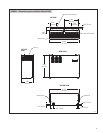
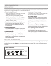
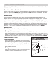
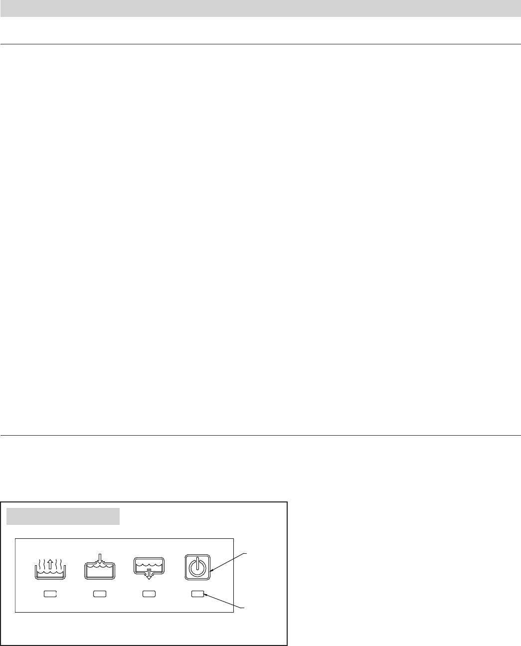
DISPLAY PANEL AND INDICATOR LIGHTS
The display panel shows operating status and troubleshooting information. See the display panel detail (Figure 5) and the table
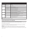
describing display panel lights (
Table 2). For more information about blinking indicator lights, see the troubleshooting section in
this manual.
OM-2028-M
On/Off
switch
Indicator
light
Steam
Fill Drain On/Off
FIGURE 5 – Display Panel
7