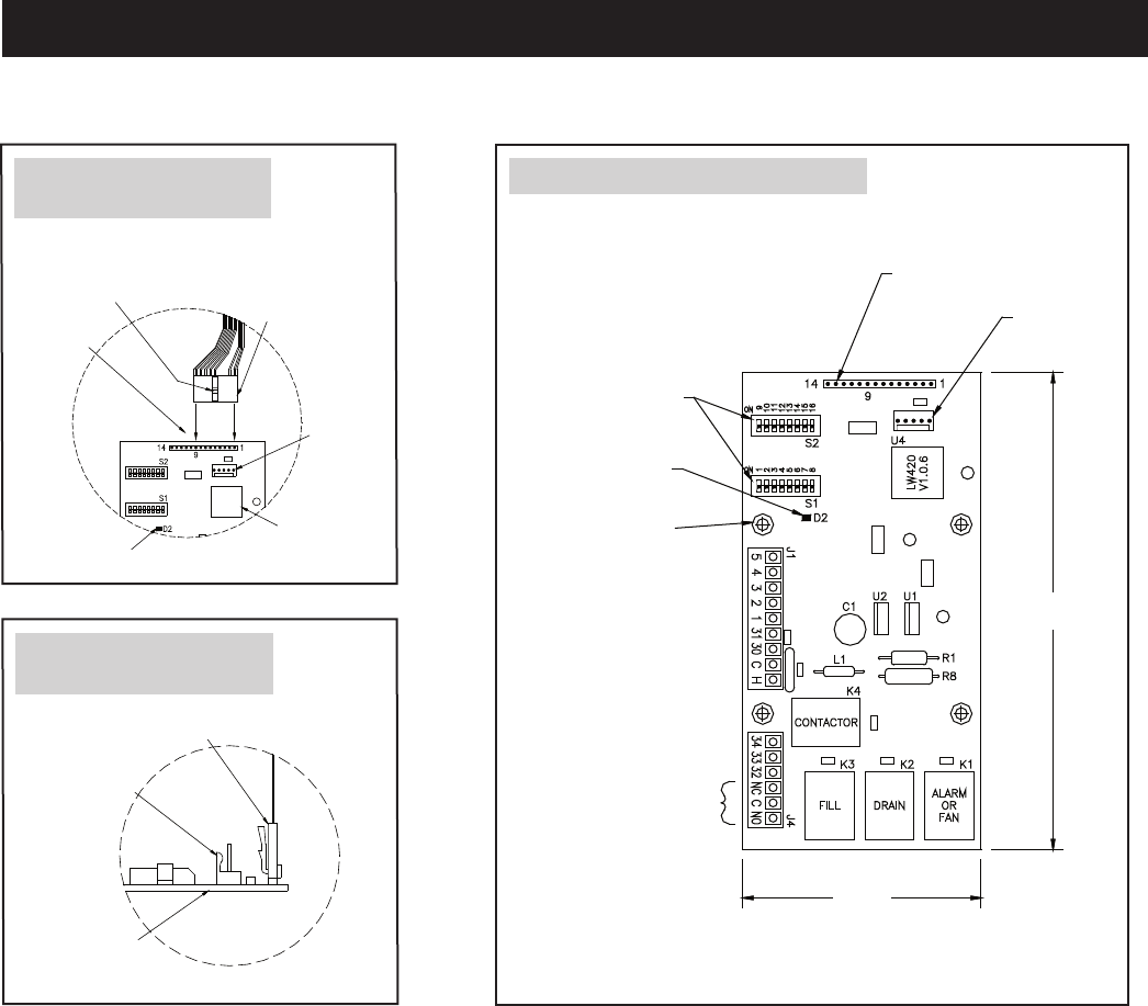
Connector tab on ribbon cable
Programming port
factory use only
Internal
controller
board
OM-2031
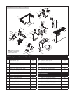
Note: See page 37 for a listing of replacement part numbers.
REPLACEMENT PARTS
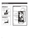
Connector tab
position
Connect to pins
1 through 9
LED indicator
Microchip
Programming
port for
factory
use only
Display panel
ribbon cable
connector
OM-2030
Internal controller board detail
FIGURE 29 – Display Panel
Ribbon Connection
FIGURE 30 – Display Panel
Connector Polarity
OM-2029
Slide switches 1 and 2
positions 1 through 16
LED indicating
power is on
Four mounting
holes 5/32” dia.
Input for display
panel ribbon cable;
see Figures 29 and 30
Programming
port for factory
use only
6”
(152 mm)
3”
(76 mm)
Water detect bottom probe input
Water detect middle probe input
Water detect top probe input
Off/on enable input
+VDC input demand signal
VDC input demand common
24 VDC supply
24 VAC common
24 VAC hot
24 VAC contactor/relay output
24 VAC fill valve output
24 VAC drain valve output
Remote alarm or
fan/blower start
Note:
Terminal blocks J1 and J4 are removable for easier wiring.
FIGURE 31 – Internal Controller Board
36


