


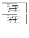
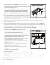
2. Remove the steam chamber (see Figure 25 for drawing item numbers):
• Hold up on the bottom of the steam chamber (Item 6 in drawing) and remove
the top mounting nuts (Items 2 and 3).
• Hold up on the bottom of the steam chamber while removing the bottom
mounting nut (Item 4). When the bottom mounting nut is removed, the
handle (Item 5) falls away from the steam chamber. Use both hands to
support the steam chamber and lower it straight down to clear heaters. Use
care not to damage gasket which is attached to the top lip of the chamber.
3. Clean the steam chamber interior by rinsing with clean water. Use a putty knife
or similar flat instrument to remove mineral deposits. Clean the strainer inside
the steam chamber located over the steam chamber drain opening. Use a wire
brush and verify that all the strainer holes are open.
4. Open the drain valve with the manual lever on the side of the actuator (Item 11) and run water through the drain valve to
remove any collected sediment.
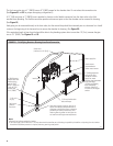
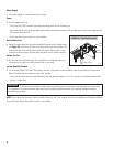
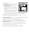
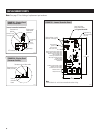
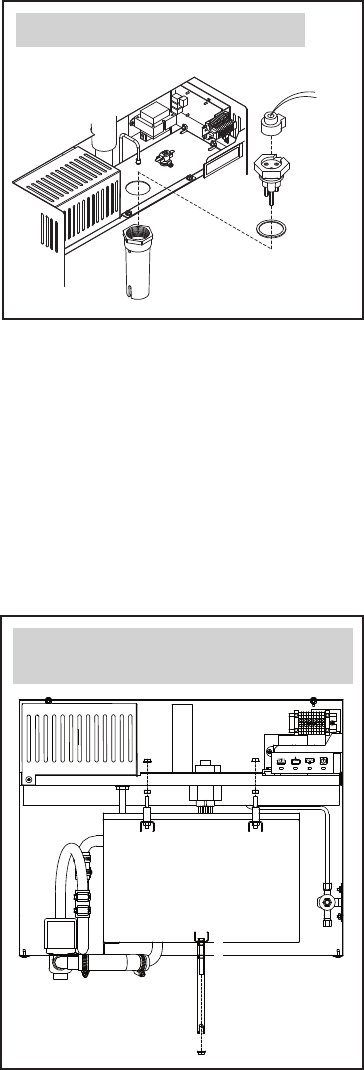
5. Unscrew the probe assembly and clean the plastic probe housing, ensuring that all passageways are clear (see
Figure 26).
Clean the probe rods using steel wool or a similar mild abrasive material. Inspect the composite plastic probe assembly for any
signs of cracking, roughness, or deterioration. Replace if necessary with Part Number 4580.
6. Install the probe assembly, probe plug, probe housing and the gasket into the cover (see
Figure 26).
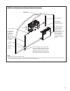
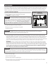
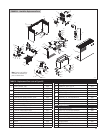
7. Re-install the chamber (see
Figure 27 for drawing item numbers):
• Using both hands, lift the chamber (Item 6 in drawing) up around the heaters
until the threaded fasteners penetrate the cover flange.
• Hold the chamber in place with one hand and pull the handle (Item 5)
toward you and up onto the threaded fastener on the front bottom of the
chamber. Make sure gasket is centered on chamber flange.
• Push the handle up against the backing nut (Item 9) and run nut (Item 4)
up the threaded fastener so it holds the handle in place.
• Tighten nut (Items 2 and 3) down on the threaded fasteners extending
through the cover flange.
• Tighten nuts (Items 2, 3, and 4) to complete the process of returning
the chamber to its position prior to removal.
• Reconnect the drain hose to the drain valve connection in the back
left corner.
• Reconnect the drain valve electrical plug.
8. Verify electrical connections:
• Verify that all power terminal screws and lugs are tight from power block to heaters.
• Verify that all electrical plugs located under the shroud are completely plugged in (transformer, contactor, drain valve,
and fill valve).
9. Move the drain valve lever back to the auto position.
10. Turn on the water supply.
OM-4052
Probe housing
Probe
assembly
Probe
plug
FIGURE 26 – Probe Rod Assembly
OM-4020
2
3
4
5
6
Chamber cover
9
1
FIGURE 27 – Chamber with
Open Fastener
30