


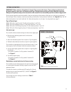
SETTING SLIDE SWITCHES
IMPORTANT: Slide switch on-off positions 1 through 16 are preset at the factory. These settings are determined
by output capacity, water type, and demand signal type. Changing these settings will affect humidifier operation.
Change on-off positions only per the instructions in this manual or as instructed by Aprilaire technical support staff.
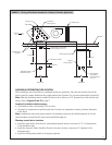
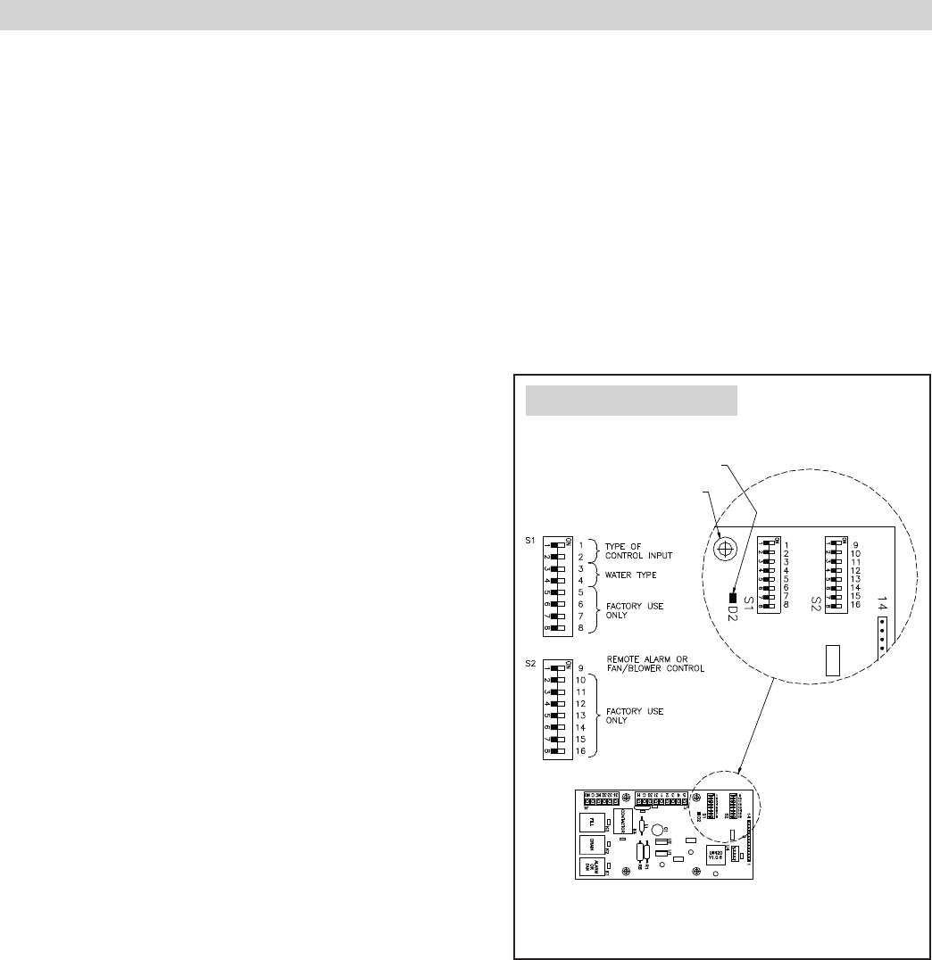
On the internal controller inside the humidifier, there are two banks of slide switches. Most are set at the factory according to
the model type. Others, however, must be set according to the details of each particular installation. See Figure 8. Note: the ‘Off’
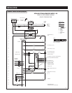
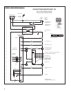
slide switch position is to the left while the ‘On’ slide switch position is to the right. For wiring details see page 21.
Type of Control Input
Model 1150 with an on/off control: S1 slide switch positions 1 and 2 Off
Model 1160 with modulating control: S1 slide switch positions 1 and 2 Off
Model 1160 with 0-10 VDC signal by others: S1 slide switch positions 1 and 2 Off
Model 1160 with 4-20 mA signal by others: S1 slide switch positions 1 and 2 On
Inlet water type
The controller allows autodrain settings for three water supply types:
• Normal water (hardness greater than 4 and less than
10 grains/gallon)
• Hard water (hardness greater than or equal to 10 grains/gallon)
• Softened water (hardness less than or equal to 4 grains/gallon)
The humidifier is preprogrammed for use with normal water. If your
water supply is hard or softened, follow the instructions below:
• For hard water supply (greater than or equal to 10 grains/gallon
of hardness):
– Set switch S1 position 3 to On; position 4 remains Off.
See Figure 8.
• For softened water supply:
– Set switch S1 position 4 to On; position 3 remains Off.
See Figure 8.
Substituting a remote fault alarm for blower starting
The humidifier may be field programmed to send a fault alarm signal
to a remote device instead of sending a signal to start the HVAC
equipment blower.
To enable this function, set slide switch S2 position 9 to On and
provide wiring to control terminals NO, O, and NC. See Figure 8
for slide switch positions.
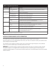
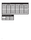
If you change any on-off settings, record them in Table 3
for future reference.
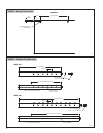
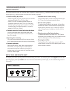
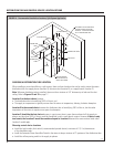
Note:
Slide switches are shown in the off position.
LED lamp
Mounting hole
Position
S1
S2
OM-2038
FIGURE 8 – Slide Switches
Internal Controller Board
11