


9
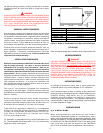
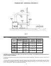
SEE FIGURE 6). AT LEAST TYPE B VENTING MUST BE USED
WITH THE STANDARD VENTING OPTION (thru-the-roof) USING
THE NATIONAL FUEL GAS CODE VENT TABLES. TYPE B VENT
PIPE
CANNOT BE USED IF THE BOILER IS VENTED
HORIZONTALLY OR AS A DIRECT VENT (SEE PAGES 12
THROUGH 15). ALL LOCAL UTILITY, STATE/ PROVINCIAL,
REGULATIONS ON VENTING MUST BE FOLLOWED.
VENT SIZING, VENT CONNECTORS, INSTALLATION AND
TERMINATION SHALL BE IN ACCORDANCE WITH THE CURRENT
EDITION OF
NATIONAL FUEL GAS CODE, ANSI Z223.1 OR CAN/
CSA-B149.1 or applicable provisions of the local building codes.
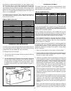
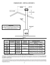
Size and install proper size vent pipe; refer to Table 6.
Horizontal runs of vent pipe shall be securely supported by
adequately placed (approximately every 4 feet [1.2 m]),
noncombustible hangers suitable for the weight and design of the
materials employed to prevent sagging and to maintain a minimum
upward slope of 1/4" per foot (2 cm/m) from the boiler to the vent
terminals. Dampers or other obstructions must not be installed in
the vent. Be sure that the vent connector does not extend beyond
the inside wall of the chimney.
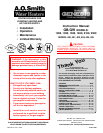
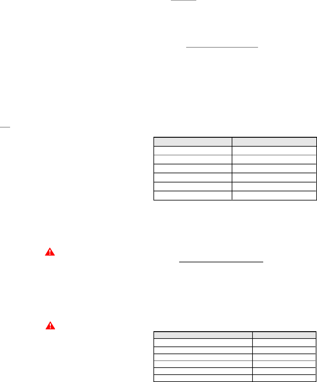
TABLE 6: VENT CONNECTION
MODEL NUMBER VENT CONNECTOR
G(B,W) 1000 10" (25.4 cm)
G(B,W) 1300 12" (30.5 cm)
G(B,W) 1500 12" (30.5 cm)
G(B,W) 1850 14" (35.6 cm)
G(B,W) 2100 14" (35.6 cm)
G(B,W) 2500 16" (40.6 cm)
For vent arrangements other than Table 10 and for proper boiler
operation, a barometric damper is required to maintain draft
between -0.02" W.C.. and -0.04" W.C. at 2 feet (0.6 m) above the
boiler vent collar.
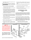
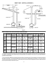
STANDARD (HORIZONTAL) VENTING, CATEGORY III
Vent sizing, installation and termination shall be in accordance
with the
NATIONAL FUEL GAS CODE, ANSI Z223.1 OR
CAN/CSA-B149.1 (Current Editions). If applicable, all local, utility,
state/provincial regulations on venting must be followed. See Table
11, Figure 7 for venting specifications. The exhaust vent pipe must
be of a type listed for use with Category III gas burning heaters such
as "Saf-T-Vent" manufactured by Heat-Fab Inc.
For Category III installations, it is important that the Installed vent
be airtight. Please insure that all joints are sealed properly during
installation. For Horizontal Vent Kit part numbers, see Table 7.
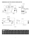
TABLE 7: HORIZONTAL VENT KITS.
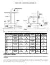
DIRECT VENT VERTICAL AND HORIZONTAL VENTING
For direct vent applications, this boiler may be vented according to
Tables 12 and 13; see Figures 8 and 9. For category III applications,
If the confined space is within a building of tight construction, air
for combustion, ventilation, and draft hood dilution must be
obtained from outdoors. When directly communicating with the
outdoors or communicating with the outdoors through vertical
ducts, two permanent openings, located in the above manner,
shall be provided. Each opening shall have a free area of not less
than one square inch per 4000 Btuh (5.5 cm
2
/kW) of the total input
of all appliances in the enclosure. If horizontal ducts are used, each
opening shall have a free area of not less than one square inch per
2000 Btuh (11 cm
2
/kW) of the total input of all appliances in the
enclosure.
(b) CANADIAN INSTALLATIONS
Ventilation of the space occupied by the boiler(s) shall be provided
by an opening for ventilation air at the highest practical point
communicating with outdoors. The total cross-sectional area shall
be at least 10% of the area of the combustion air opening but in no
case shall the cross-sectional area be less than 10 square inches
(64.5 cm
2
).
In addition to the above, there shall be permanent air supply
opening(s) having a cross-sectional area of not less than 1 square
inch per 7,000 BTUH (3.2 cm
2
/kW) up to and including 1,000,000
BTUH plus 1 square inch per 14,000 BTU (1.6 cm
2
/kW) in excess of
1,000,000 BTUH. This opening(s) shall be located at, or ducted to,
a point neither more than 18" (46.0 cm) nor less than 6 inches (15.2
cm) above the floor level.
Where power vented equipment is used in the same room as the
boiler, sufficient air openings must be supplied. UNDERSIZED
OPENINGS MAY RESULT IN INSUFFICIENT AIR FOR
COMBUSTION.
Where an exhaust fan is installed in the same room with a boiler,
sufficient openings for air must be provided in the walls.
UNDERSIZED OPENINGS WILL CAUSE AIR TO BE DRAWN INTO
THE ROOM THROUGH THE CHIMNEY, CAUSING POOR
COMBUSTION. SOOTING MAY RESULT WITH AN INCREASED
RISK OF ASPHYXIATION.
VENTING
CAUTION
WHEN VENTING THE GENESIS BOILER THROUGH AN
OVERSIZED CHIMNEY (INCLUDING MASONRY CHIMNEYS),
ADDITIONAL CARE MUST BE EXERCISED TO ASSURE PROPER
DRAFT. FOR PROPER OPERATION, A MINIMUM DRAFT OF -0.02"
W.C. AND A MAXIMUM DRAFT OF -0.04" W.C. MUST BE MAINTAINED.
IN INSTANCES OF EXCESSIVE DRAFT, A BAROMETRIC DAMPER
MAY BE REQUIRED TO ASSIST IN MAINTAINING THE PROPER
DRAFT. DRAFT SHOULD BE MEASURED 2 FEET (0.6 M) ABOVE
THE BOILER VENT COLLAR.
WARNING
THE INSTRUCTIONS IN THIS SECTION ON VENTING THE BOILER
MUST BE FOLLOWED TO AVOID CHOKED COMBUSTION OR
RECIRCULATION OF FLUE GASES. SUCH CONDITIONS CAUSE
SOOTING OR RISKS OF FIRE AND ASPHYXIATION.
This boiler is approved to be vented as a Category I, Category III
(horizontal venting), or a Direct Vent appliance. The Horizontal and
Direct Venting options require a special vent kit.
STANDARD (VERTICAL) VENTING, CATEGORY I
THIS BOILER MAY BE VENTED ACCORDING TO TABLE 10 (ALSO
HORIZONTAL VENT KIT MODEL
211426 G(B,W) 1000
211426-1 G(B,W) 1300
211426-1 G(B,W) 1500
211426-2 G(B,W) 1850
211426-2 G(B,W) 2100
211426-3 G(B,W) 2500