


42
when an error is detected. It will also go to this screen upon
power-up if an error was still valid when power was turned off.
NOTE: Errors are cleared from this screen by pressing the
"select" key.
• Error History Screen:
This screen displays a list of the last 9 errors (with time stamps)
that have occurred. The last error to occur is displayed first. If a
new error occurs this screen is presented to display the error.
• Reload Defaults Screen:
From this screen the user can restore the factory default values
for screen adjustable configurations by pressing the Select key.
The values restored are as follows:
GW Models
Oper Setpnt (Operating Setpoint) - 145° F (63° C)
Stage1 Diff (Operating Setpoint Differential) = 3° F (2° C)
Stage2 Diff (Operating Setpoint Differential) = 6° F (3° C)
Hi Limit (High LImit Setpoint) = 210° F (99° C)
Hi Limit Dif (High Limit Differential) = 20° F (11° C)
GB Models
Oper Setpnt (Operating Setpoint) = 190° F (88° C)
Stage1 Diff (Operating Setpoint Differential) = 3° F (2° C)
Stage2 Diff (Operating Setpoint Differential) = 6° F (3° C)
Hi LImit (High LImit Setpoint) = 230° F (110° C)
Hi Limit Dif (High Limit Differential) = 20° F (11° C)
Both Models
Tempert Units (Temperature Units) = F
Post Cir Secs (Post Circulation pump delay = 45 seconds
Network Address (Network Address) = (none)
UIM Touch Switches
Below the LCD display are five touch switches or keys, that the
operator uses to operate the system.
• Menu Key:
Pressing this key activates the menu screen where the other
screens can be accessed.
• Select Key:
This key performs several functions. Screens can be selected
from the menu screen by pressing this key when the">" appears
next to the screen desired.
On the User Settings screen items that appear next to a ">"
symbol can be selected with this key. If a setpoint configuration
item is selected, the ">" will then flash slowly to indicate that the
item has been selected. The Up and Down keys are then used
to change its value.
From the Current Error Screen this key is used to reset the
system from an error:
• Up and Down Keys:
These keys are used to move upwards and downwards in
screens to reach a desired item and to change setpoints and
user settings. They have an auto increment/decrement feature
for some of the configurations and values. When you first press
one of the keys and value changes by 1 count, then wait 1/2
second and changes slowly until the key is released or if held
for 3 or more seconds it will change the value quickly.
• Help Key:
Pressing the Help key from any screen displays helpful
information about that screen. From the menu screen, general
help information is displayed as to how to use the user interface.
To return to the previous screen press the Help or Select keys,
or press Menu key to go to the menu screen. If a small down
arrow appears in the lower right hand corner then there is off
screen content below what is displayed. Press the down arrow
to scroll down to this information. After scrolling down an up
arrow will appear in the upper right hand corner to indicate off
screen content above what is displayed.
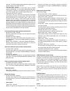
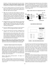
UIM LED's
The three LED's to the right of the LCD indicate the status of the
overall system. The red LED indicates that a fault has been detected
and the system has stopped running. It is on continuously for soft
faults and flashes for hard faults. The Yellow LED indicates that
the boiler is in a ready mode waiting for a call for heat command.
When on continuously the Green LED indicates that the system is
in the heating mode. If it is flashing it indicates that the UIM is in the
initialization mode and the touch switches are being calibrated.
On these boilers there are also eight LED's on the lower right that
indicate the state of the individual FCB's. The red LED's are only on
when the main red LED is on and indicate which FCB has the error.
The green LED indicates when flame is proved on that particular
stage, unless the dipswitch for sensing flame is turned off. Then
the LED indicates that the gas valve has turned on.
Fault Messages and Troubleshooting Guide
The EMC5000 system does excessive self-diagnostics and
displays detected faults on the UIM display in an easy to read
manner. There are approximately 80 different faults that can be
detected. Some of the faults are caused by internal problems and
some by external causes. The faults create different types of system
lockouts (shut down). Hard lockouts are serious problems that
require the user to manually restart system. Soft lockouts can be
reset by the user or after 60 minutes the system will automatically
clear the error and restart. Auto Reset lockouts will monitor the
cause of the fault and if the fault clears itself the system reset itself.
The fault is recorded and the system immediately resets itself.
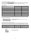
The following table shows the fault messages and some possible
troubleshooting hints:
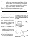
TROUBLESHOOTING IGNITION SYSTEM
Fault Messages and Lockout Status (* = stage number: 1, 2, 3, or 4)
FAULT DISPLAYED DESCRIPTION RED LED LOCKOUT
“Display Fail” Communications with UIM interrupted Continuous Auto Reset
Check communication cable to UIM. Try moving to other Internal Communications connector on CCB.
Also check the connectors where the cable is plugged in for best connecting wires.
“Comm. Fail Stg.*” Communications with FCB interrupted Continuous Auto Reset
Same as above. Also try swapping FCB and UIM communications cables.
“Low AC Voltage” Line voltage less than 90 vac Continuous Auto Reset
Check incoming power line for loss of voltage. May also be caused by a power line brown-out (momentary
loss of voltage)