


38
followed by 15-second inter-purge period, then the system
returns to step 7, if the "Trial for Ignition" dipswitch is set for
three (3) tries. If the dipswitch is set for one (1) trial, the system
will declare an error and boiler will require resetting the control.
10. If a flame is detected, stage two will be activated and start its
blower. Once the blower air has been proven, igniter two will
begin trial for ignition cycle as above, (this is not the case for
model 1000, which has only one igniter).
11. Stage three will activate upon flame detection on stage two.
The gas valve will open five seconds following call for heat
and gas flow will continue if flame signal is detected. (On 4-
stage firing system, the blower associated with stage three
will start and once the blower air has been proven, the ignition
cycle will take place as above. If flame is not proven, a 15-
second inter-purge period will be activated followed by another
trial for ignition).
12. All stages will remain running until the set point for a given stage
is satisfied. The last stage will drop out first followed by inter-
stages then stage one will drop out last. Note: Once a stage is
satisfied, the blower associated with that stage will continue for
15-second post purge period.
13. Once all the stages have been satisfied, the boiler pump will
continue to run for the programmed post-circulate cycle.
14. The control now enters the idle state as displayed by the
"Standby" LED. The control will continue to monitor heat
demand and state of other system devices. Upon a drop of
water temperature below the set parameters, the control will
return to step 5 and repeat the entire operating cycle. Note:
Any fault detection, during standby or running modes, will halt
the heating sequence and shift the system to the service mode
where the detected fault will be displayed.
NOTE: In standby and running modes the system constantly
monitors the signals and the internal operation for faults. Any
detected fault will halt the heating sequence and shift the system
to the service mode, where the detected fault will be displayed.
Temperature Setpoints (System Control Algorithm)
The boiler has a hysteresis type control, which means that it will
begin heating the water when the temperature sensed by the control
probe (inlet or tank) falls below the operating setpoint minus the
differential setpoint for stage 1. It will stop heating the water when
the temperature rises to the operating setpoint. If the system has
multiple stages then the differential setpoint for each stage is also
subtracted from the operating setpoint. The following examples
will further explain this operation.
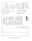
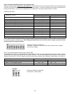
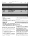
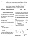
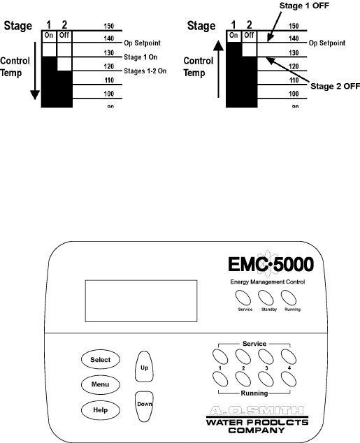
Setup: 2 stage system, operating setpoint - 140, stage 1 to 2
differential setpoints = 10.
Example 1. Temperature begins at 150 and drops to 90, see Figure
20A. At 140 the system remains in idle mode. As the temp drops to
130 (140-10) stage 1 turns on and stage 2 remains off. At 120 stage
2 also turns on.
Example 2. Temperature begins at 90 and rises to 150, see Figure
20B. At 100 both stages are on. (This is the case when a boiler is
first started and the controlling temperature is below the operating
setpoint minus all of the differential setpoints. At that time both stages
are turned on, in sequence from 1 to 2. At 130 stage 2 turns off. At
140 both stages are off.
Stages 1 and 2 will turn on in sequence from 1 to 2.
FIGURE 20 A. FIGURE 20 B.
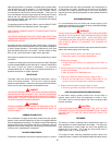
UIM OPERATING PROCEDURES
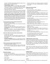
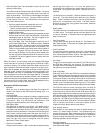
FIGURE 21. UIM, USER INTERFACE MODULE
The UIM receives commands from the user and displays operational
information to the user via an LCD (liquid crystal display) up to
eleven LED's, and five touch switches. The LCD provides
information to the user by the use of 10 menu-activated screens.
Within each of the screens, helpful information can be displayed
by pressing the "Help" button. The LED's visually inform the user
about the mode the system is in. The touch switches allow the
user to control the operation of the system. The operation of these
parts is described in the following section:
UIM Screens:
On all screens a double vertical bar appears on the right side of the
display each time a key is touched to indicate that a key has been
activated. On several screens an indicator ">" appears on the left
side of the display to indicate the active line. The "Up/Down" keys are
used to move the indicator to the desired line and the "Select" key is
pressed to select the line. Also, on most of the screens, up/down
arrows appear on the right side of the screen to indicate that there is
additional lines either above or below the displayed four lines.