


6
DIFFERENTIAL PRESSURE SWITCH
The differential pressure switch ensures that a sufficient differential
exists between the air pressure in the pre-mix chamber and the inlet
of the burner for safe, combustion and proper low NO
x
emission. The
switch has two pressure taps marked "+" (positive) and "-" (negative).
Silicone tubing is run from the positive pressure tap of the switch to a
tap on the control panel to measure the air pressure in the pre-mix
chamber. The negative pressure tap measures the pressure taken at
the burner's auxiliary tube. Connections can be seen by removing the
lower front jacket panel. It is important that this panel remain sealed
at all times while the boiler is operating.
The differential pressure switch is normally open and closes when
the combustion blower starts.
BLOCKED FLUE PRESSURE SWITCH
The blocked flue pressure switch ensures that the vent system is
clear. This pressure switch is normally closed and only opens on
fault conditions.
FLAME SENSOR
The flame sensor detects the flame presence on burner's ports. If
no flame is sensed, the gas valve(s) will close automatically. If no
flame is sensed on three ignition trials the boiler will lock out. In the
event of a lockout, depress the SELECT button on the UIM to restart
the boiler.
WATER FLOW SWITCH
The water flow switch is installed at the boiler outlet to prevent burner
operation in the event of inadequate water flow through the boiler. It
is a normally open switch that will close its contacts when increasing
water flow rate is detected. The water flow switch is factory-set, but
may require field adjustment. The contacts will open when the flow
rate drops below the adjusted setting causing the gas valve(s) to
close which will turn off the gas to the burners.
LIMIT CONTROLS
CAUTION
LIMIT CONTROLS ARE SAFETY DEVICES AND ARE NOT TO BE
USED AS AN OPERATING CONTROL (THERMOSTAT).
The "G(B/W)" models incorporate an outlet water probe consisting
of two limit controls:
1. An adjustable automatic reset limit control, that can be set
as high as either 210°F (99°C) or 235°F (113°C) depending on
the application.
2. A fixed manual reset limit (ECO) factory set at 244°F
(118°C). If the manual reset should open due to high
temperature, the gas valves will close and the unit will go into
lockout. If lockout occurs, push the SELECTION button on the
UIM to restart the boiler.
ON/OFF SWITCH
The ON/OFF switch is a single-pole, single-throw rocker switch.
The switch provides 120VAC from the line source to the boiler.
COMBUSTION AIR BLOWER
Provides air for combustion process. The blower settings are
adjustable through the use of the air shutter, however, blowers are
set at the factory and might require slight adjustment depending
on site installation.
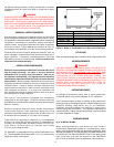
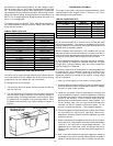
TANK PROBE
FOR HOT WATER SUPPLY SYSTEMS (GW models), a tank probe
is supplied with each hot water supply boiler.
Note: The tank probe must be designated as the controlling probe
using dip switch "4" on Central Control Board (Figure 17) before it
can be used for (GW) hot water supply applications.
"Pigtails" of field-supplied wires should be spliced to "pigtails" of
tank probe and connected to terminal block in the 24VAC junction
box. See Figure 12 for the tank probe installation. Follow the
instructions in the "TANK PROBE INSTALLATION PROCEDURE".
See page 18.
FOR HOT WATER HEATING SYSTEMS (GB models), a tank probe
is not supplied with the GB models due to the many various
types of systems and operating conditions. A tank probe can
be used as an option to control loop temperature and unit
staging. Additionally, the inlet temperature probe can be used
as the loop thermostat in some heating applications. The tank
probe connects to designated wires in the junction box at the
rear of the boiler. Do not operate this boiler using the internal
high limits only, use a tank probe or operating thermostat to
control system temperatures.
Note: The tank probe or additional 24VAC devices must be identified
using Dipswitches on Central Control Board before they are
recognized as a part of the heating system; see Table 5. Refer to
"Control System" section for more information about dipswitch
settings.
CIRCULATING PUMP
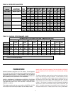
The pump flow rate should not exceed the maximum
recommended flow rate; see Table 5.
FOR HOT WATER SUPPLY SYSTEMS (GW models), ordered with
the circulator as an integral part of the boiler; the pump has been
lubricated at the factory, and future lubrication should be in
accordance with the motor manufacturer's instructions provided
as supplement to this manual.
FOR HOT WATER HEATING SYSTEMS (GB models or GW models
ordered without circulator), the circulator is NOT provided and
must be field-installed.
LOW WATER CUTOFF (Not Supplied)
If low water level protection is required by the authorities having
jurisdiction, a low water cutoff switch should be installed
next to the boiler in the outlet water line as shown in
"HYDRONIC INSTALLATION" section; see page 16. The switch
should receive periodic (every six months) inspection to assure
proper operation. A low water cutoff device of the float type should
be flushed every six months.