


7
DRAIN VALVE (Not Supplied)
Additional drain valves must be obtained and installed on each boiler
and tank for draining purposes.
SAFETY RELIEF VALVES
Your local code authority may have other specific relief valve
requirements not covered below.
WARNING
THE PURPOSE OF A SAFETY RELIEF VALVE IS TO AVOID
EXCESSIVE PRESSURE WHICH MAY CAUSE TANK EXPLOSION,
SYSTEM OR BOILER DAMAGE.
TO AVOID WATER DAMAGE A DRAIN LINE MUST BE CONNECTED
TO A SAFETY RELIEF VALVE FOR DIRECT DISCHARGE TO A SAFE
LOCATION. A DRAIN LINE MUST NOT BE REDUCED FROM THE
SIZE OF THE VALVE OUTLET AND IT MUST NOT CONTAIN ANY
VALVES BETWEEN THE BOILER AND THE RELIEF VALVE OR
THE RELIEF VALVE AND THE DRAIN EXIT. IN ADDITION, THERE
SHOULD NOT BE ANY RESTRICTIONS IN A DRAIN LINE NOR
SHOULD IT BE ROUTED THROUGH AREAS WHERE FREEZING
CONDITIONS MIGHT OCCUR. DO NOT THREAD OR CAP THE
DRAIN LINE EXIT. RESTRICTING OR BLOCKING A DRAIN LINE
WILL DEFEAT THE PURPOSE OF THE RELIEF VALVE AND MAY
CREATE AN UNSAFE CONDITION. INSTALL A DRAIN LINE WITH
A DOWNWARD SLOPE SUCH THAT IT NATURALLY DRAINS
ITSELF.
If any safety relief valve is replaced, the replacement valve must
comply with the latest version of the ASME Boiler and Pressure
Vessel Code, Section IV (HEATING BOILERS). Select a relief valve
with a discharge rating NOT less than the boiler input, and a set
pressure NOT exceeding the working pressure of any component
in the system.
The storage tank temperature and pressure relief valve must
comply with the applicable construction provisions of the Standard
for Relief Valves for Hot Water Supply Systems, ANSI Z21.22-CSA-
4.4 (current edition). The valve must be of the automatic reset type
and not embody a single-use type fusible plug, cartridge or linkage.
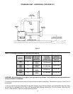
FOR HOT WATER HEATING SYSTEMS, the boilers are shipped
with a 50 psi pressure relief valve. This relief valve is factory
installed on the water outlet header of the boiler.
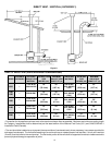
FOR HOT WATER SUPPLY SYSTEMS, the boilers are shipped
with a 125 psi pressure relief valve. This relief valve is factory
installed on the water outlet header of the boiler. This ASME-rated
valve has a discharge capacity that exceeds the maximum boiler
input rating and a pressure rating that does not exceed the
maximum working pressure shown on the boiler rating plate.
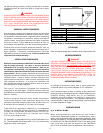
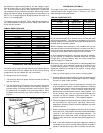
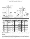
In addition, a CSA design-certified and ASME-rated temperature
and pressure (T & P) relief valve must be installed on every water
storage tank in the hot water supply system; see
Figures 11 and 13.
The T & P relief valve should have a temperature rating of 210°F
(99°C), a pressure rating NOT exceeding the lowest rated working
pressure of any system component, and a discharge capacity
exceeding the total input of the water boilers supplying water to the
storage tank.
Locate the T & P relief valve (a) in the top of the tank, or (b) in the
side of the tank on a center line within the upper six (6) inches
(15 cm) of the top of the tank. The tapping shall be threaded in
accordance with the latest edition of the Standard for Pipe Threads,
General Purpose (inch), ANSI/ASME B1.20.1. The location of, or
intended location for, the T & P relief valve shall be readily
accessible for servicing or replacement.
INSTALLATION INSTRUCTIONS
REQUIRED ABILITY
INSTALLATION OR SERVICE OF THIS BOILER REQUIRES ABILITY
EQUIVALENT TO THAT OF A LICENSED TRADESMAN IN THE FIELD
INVOLVED. PLUMBING, AIR SUPPLY, VENTING, GAS SUPPLY AND
ELECTRICAL WORK ARE REQUIRED.
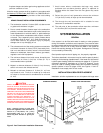
LOCATION
When installing the boiler, consideration must be given to proper
location. The location selected should be as close to the stack or
chimney as practical with adequate air supply and as centralized
with the piping system as possible. The location should also be
such that the gas ignition system components are protected from
water (dripping, spraying, etc.) during appliance operation and
service (circulator replacement, control replacement, etc.)
• THE BOILER MUST NOT BE INSTALLED ON CARPETING.
• THE BOILER SHOULD NOT BE LOCATED IN AN AREA WHERE
IT WILL BE SUBJECT TO FREEZING.
• THE BOILER SHOULD BE LOCATED NEAR A FLOOR DRAIN.
• THE BOILER SHOULD BE LOCATED IN AN AREA WHERE
LEAKAGE FROM THE BOILER OR CONNECTIONS WILL NOT
RESULT IN DAMAGE TO THE ADJACENT AREA OR TO LOWER
FLOORS OF THE STRUCTURE.
WHEN SUCH LOCATIONS CANNOT BE AVOIDED, A SUITABLE
DRAIN PAN SHOULD BE INSTALLED UNDER THE BOILER. Such
pans should be fabricated with sides at least 2-1/2" (6.5 cm) deep,
with length and width at least 2" (5.1 cm) greater than the dimensions
of the boiler and must be piped to an adequate drain. The pan
must not restrict combustion air flow.
WARNING
THERE IS A RISK IN USING FUEL BURNING APPLIANCES IN
ROOMS OR AREAS WHERE GASOLINE, OTHER FLAMMABLE
LIQUIDS OR ENGINE DRIVEN EQUIPMENT OR VEHICLES ARE
STORED, OPERATED OR REPAIRED. FLAMMABLE VAPORS ARE
HEAVY AND TRAVEL ALONG THE FLOOR AND MAY BE IGNITED
BY THE IGNITER OR MAIN BURNER FLAMES CAUSING FIRE OR
EXPLOSION. SOME LOCAL CODES PERMIT OPERATION OF GAS
APPLIANCES IF INSTALLED 18 INCHES (46.0 CM) OR MORE
ABOVE THE FLOOR. THIS MAY REDUCE THE RISK IF LOCATION
IN SUCH AN AREA CANNOT BE AVOIDED.
FLAMMABLE ITEMS, PRESSURIZED CONTAINERS OR ANY
OTHER POTENTIAL FIRE HAZARDOUS ARTICLES MUST NEVER
BE PLACED ON OR ADJACENT TO THE BOILER.
OPEN CONTAINERS OF FLAMMABLE MATERIAL SHOULD NOT
BE STORED OR USED IN THE SAME ROOM WITH THE BOILER.
A hot water boiler installed above radiation level or as required by