


8
the authority having jurisdiction, must be provided with a low water
cutoff device either as a part of the boiler or at the time of boiler
installation.
WARNING
UNDER NO CIRCUMSTANCES SHOULD THE EQUIPMENT ROOM
WHERE THE BOILER IS INSTALLED EVER BE UNDER NEGATIVE
PRESSURE. PARTICULAR CARE MUST BE TAKEN WHEN
EXHAUST FANS, COMPRESSORS, AIR HANDLING EQUIPMENT,
ETC., MAY INTERFERE WITH THE COMBUSTION AND
VENTILATION AIR SUPPLIES OF THIS BOILER.
CHEMICAL VAPOR CORROSION
Heat exchanger corrosion and component failure can be caused
by the heating and breakdown of airborne chemical vapors. Spray
can propellants, cleaning solvents, refrigerator and air conditioning
refrigerants, swimming pool chemicals, calcium and sodium
chloride, waxes, and process chemicals are typical compounds
which are corrosive. These materials are corrosive at very low
concentration levels with little or no odor to reveal their presence.
Products of this sort should not be stored near the boiler. Also, air
which is brought in contact with the boiler should not contain any of
these chemicals. If necessary, uncontaminated air should be
obtained from remote or outside sources. Failure to observe this
requirement will void the warranty.
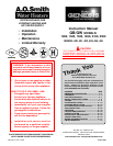
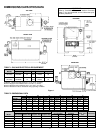
INSTALLATION CLEARANCES
Sufficient area should be provided at the front and sides of the
unit for proper servicing. For ease of service, minimum
clearances of 24" (61.0 cm) in the front and 18" (46.0 cm) on
the sides are recommended. It is important that the minimum
clearances be observed to allow service to the control box and
other controls. Observing proper clearances will allow service to
be performed without movement or removal of the boiler from its
installed location. Failure to observe minimum clearances may
require removal of the boiler in order to service such items as the
heat exchanger and burners. In a utility room installation, the
door shall be wide enough to allow the boiler to enter or to permit
the replacement of another appliance.
Two inch (5.1 cm) clearance is allowable from combustible
construction to hot water pipes. Sufficient clearance should be
provided at one end of the boiler to permit access to heat exchanger
tubes for cleaning.
Access to control box items such as the Central Control Board,
Flame Control Boards, Power Distribution Board and wiring
harnesses is provided through a panel on the left side of the unit.
A minimum service clearance of 18" (46.0 cm) is required.
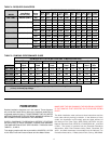
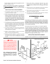
These boilers are approved for installation on noncombustible
flooring in an alcove with minimum clearance to combustibles of:
3 inches (7.6 cm) Right Side, and Back; 6 inches (15.2 cm) Top;
Front, Alcove; 12 inches (30.5 cm) Left Side; and 6 inches
(15.2 cm) surrounding the Vent.
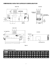
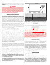
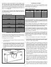
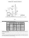
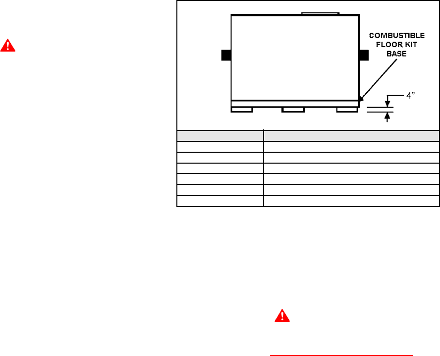
For installation on combustible flooring use the Combustible Floor
Kit. The combustible floor kit base adds 4" (10.1 cm) to the overall
height of the boiler. See Figure 3.
MODEL COMBUSTIBLE BASE KIT NUMBER
G(B,W) - 1000 211093
G(B,W) - 1300 211093-1
G(B,W) - 1500 211093-2
G(B,W) - 1850 211093-3
G(B,W) - 2100 211093-4
G(B,W) - 2500 211093-5
Figure 3. Boiler on Combustible Floor Base and Kit Numbers.
LEVELLING
Each unit must be checked after installation to be certain that it is level.
AIR REQUIREMENTS
WARNING
FOR SAFE OPERATION, AN AMPLE SUPPLY OF AIR MUST BE
PROVIDED FOR PROPER COMBUSTION AND VENTILATION IN
ACCORDANCE WITH THE NATIONAL FUEL GAS CODE, ANSI
Z223.1 OR CAN/CSA-B149.1 CURRENT EDITION OR APPLICABLE
PROVISIONS OF THE LOCAL BUILDING CODES. AN
INSUFFICIENT SUPPLY OF AIR MAY RESULT IN A YELLOW,
LUMINOUS BURNER FLAME, CARBONING OR SOOTING OF THE
FINNED HEAT EXCHANGER, OR CREATE A RISK OF
ASPHYXIATION. DO NOT OBSTRUCT THE FLOW OF
COMBUSTION AND VENTILATION AIR.
UNCONFINED SPACE
In buildings of conventional frame, brick or stone construction,
unconfined spaces may provide adequate air for combustion.
If the unconfined space is within a building of tight construction
(buildings using the following construction: weather stripping, heavy
insulation, caulking, vapor barrier, etc.), air for combustion,
ventilation, must be obtained from outdoors or spaces freely
communicating with the outdoors. The installation instructions for
confined spaces in tightly constructed buildings must be followed
to ensure adequate air supply.
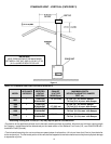
CONFINED SPACE
(a) U. S. INSTALLATIONS
When drawing combustion and dilution air from inside a
conventionally constructed building to a confined space, such a
space shall be provided with two permanent openings, ONE
WITHIN 12 INCHES OF THE ENCLOSURE TOP AND ONE WITHIN
12 INCHES OF THE ENCLOSURE BOTTOM. Each opening shall
have a free area of at least one square inch per 1000 Btu/hr
(22 cm
2
/k W) of the total input of all appliances in the enclosure.