


22
Where it is necessary to use more than the average number of
pipe fittings i.e. elbows, tees, and valves in gas supply line, use
a pipe larger than specified to compensate for increased
pressure drop.
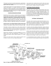
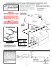
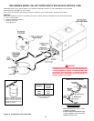
Gas control trains are unique for each Genesis II unit. Stages one,
two and three run sequentially left to right on the smaller units (GB/
GW 1000 -1500) while stage one is located in different positions on
the larger units. Gas manifold diagrams are depicted in Figure 14.
WIRING CONNECTIONS
ALL ELECTRICAL WORK MUST BE INSTALLED IN
ACCORDANCE WITH THE NATIONAL ELECTRICAL CODE,
ANSI/NFPA 70 OR CSA-C22.1 CURRENT EDITION AND MUST
CONFORM TO LOCAL REGULATIONS.
AN ELECTRICAL GROUND IS REQUIRED TO REDUCE RISK OF
ELECTRIC SHOCK OR POSSIBLE ELECTROCUTION.
Make the
ground connection to the wire provided in the electrical supply
junction box on the boiler.
Grounding and all wiring connected to this boiler must conform to
the local code authority having jurisdiction or, in the absence of such
requirements, with the
National Electrical Code, ANSI/NFPA 70 or
CSA-C22.1 current edition.
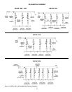
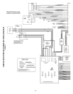
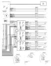
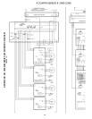
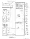
The Central Control Board and Flame Control Boards that make
up the control system are micro-processor based which make
them vulnerable to voltage and amperage fluctuations in the
power supply. Refer to Connection and Schematic Diagrams.
See Figures 15 and 16.
IF ANY OF THE ORIGINAL WIRE, AS SUPPLIED WITH THE
APPLIANCE, MUST BE REPLACED, IT MUST BE REPLACED WITH
TYPE 105°C WIRE OR ITS EQUIVALENT.
The Genesis Hot Water Supply Boiler must be connected to a single
phase dedicated and isolated line source: 120 volts, 60Hz, and 30 Amps.
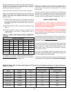
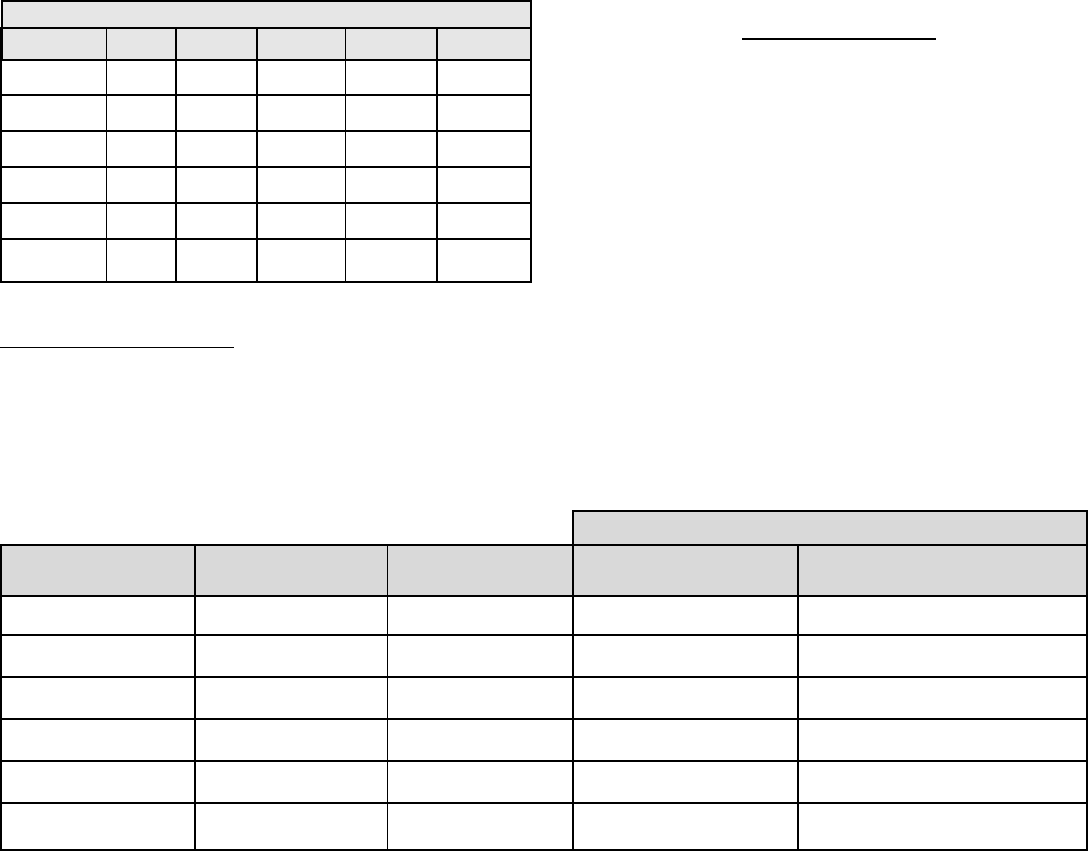
TABLE 18. Orifice Size for Natural and Propane (LP) Gases (U.S. and Canada Installations, for high altitude up to
4,500 ft. (1,372 m).
Drill Size
Input Rating Number of
Model BTU/HR Burners Natural (4 Holes) Propane (3 Holes)
G(B,W) 1000 990,000 10 0.111" 0.075"
G(B,W) 1300 1,300,000 13 0.111" 0.075"
G(B,W) 1500 1,500,000 15 0.111" 0.075"
G(B,W) 1850 1,850,000 19 0.111" 0.075"
G(B,W) 2100 2,100,000 21 0.111" 0.075"
G(B,W) 2500 2,490,000 25 0.111" 0.075"
Gas Pipe sizing may be larger than heater connections on
installations where a significant run of piping is required. To prevent
damage, care must be taken not to apply too much torque when
attaching gas supply pipe to gas inlet.
Fittings and unions in the gas line must be metal to metal type.
Apply joint compounds (pipe dope) sparingly and only to the male
threads of pipe joints. Do not apply compound to the first two
threads. Use compounds resistant to the action of liquefied
petroleum gases.
1. CORRECT GAS - Make sure gas on which the boiler will operate
is the same as that specified on the rating plate. Do not install
the boiler if equipped with a different type of gas. Consult your
gas supplier.
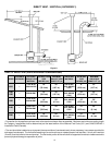
2A. SIZING GAS SUPPLY LINE (For single boiler installations). See
Table 17.
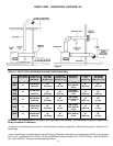
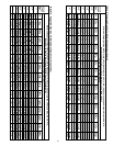
2B.SIZING GAS SUPPLY LINE (For multiple installations of two
or more boilers). See Tables 15 (Natural Gas) and 16
(Propane Gas).
TABLE 17. SINGLE UNIT INSTALLATION, SUGGESTED
PIPE SIZE
DISTANCE FROM METER
BTU INPUT 0-50' 51-100' 101-200' 201-300' 301-500'
990,000 2" 2" 2 1/2" 2 1/2" 2 1/2"
1,300,000 2" 2 1/2" 2 1/2" 3" 3"
1,500,000 2" 2 1/2" 3" 3" 3 1/2"
1,850,000 2 1/2" 2 1/2" 3" 3" 3 1/2"
2,100,000 2 1/2" 3" 3" 3 1/2" 4"
2,500,000 2 1/2" 3" 4" 4" 4 1/2"
Use Tables 15 or 16, which are taken from ANSI booklet Z223.1,
NATIONAL FUEL GAS CODE, or CAN/CSA-B149.1 (current edition)
to size iron pipe or equivalent gas supply line.