


11
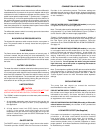
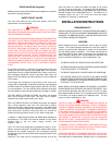
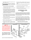
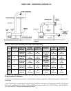
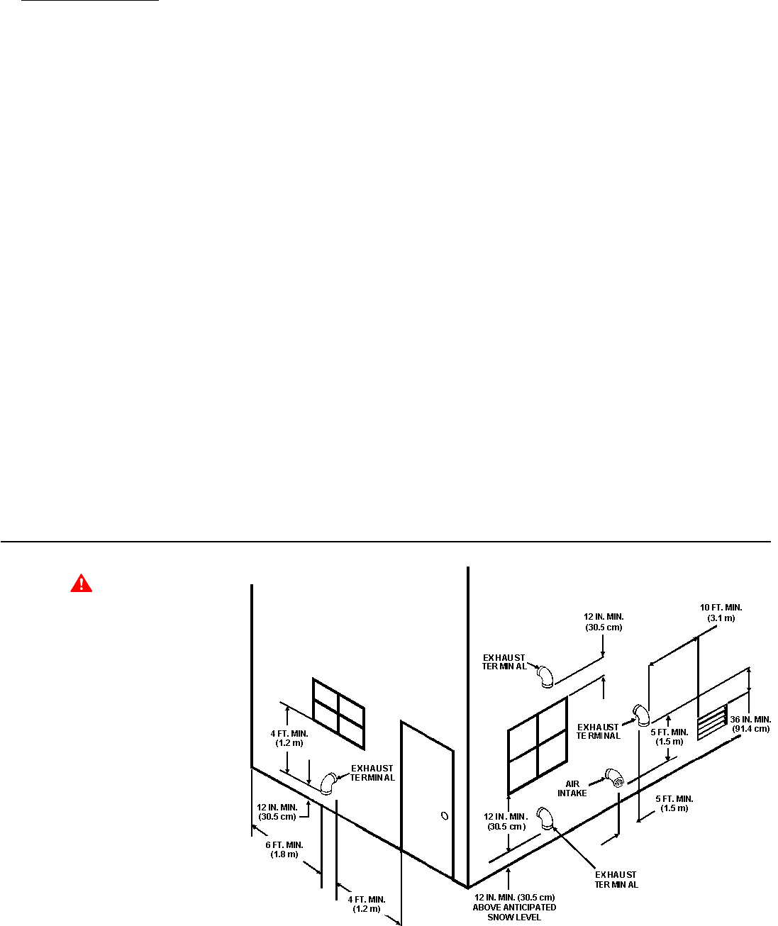
Figure 5. Vent Termination Installation Clearances
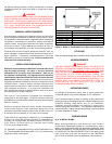
CAUTION
DIRECT VENTING INTO DEAD AIR SPACES
SUCH AS ALLEYS, ATRIUMS AND INSIDE
CORNERS CAN CAUSE RECIRCULATION OF
FLUE GASES. RECIRCULATION OF FLUE
GASES WILL CAUSE SOOTING, PREMATURE
FAILURE OF THE HEAT EXCHANGER AND
ICING OF THE COMBUSTION AIR INTAKE
DURING SEVERE COLD WEATHER. TO
PREVENT THE RECIRCULATION OF FLUE
GASES, MAINTAIN AS MUCH DISTANCE AS
POSSIBLE BETWEEN THE COMBUSTION AIR
INTAKE AND THE EXHAUST VENT TERMINAL.
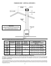
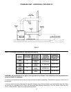
STANDARD VENTING DIRECT VENT APPLICATIONS
Note: Venting system of other than
direct-vent appliance shall terminate at
least 4 ft. (1.2 m) below, 4 ft. (1.2 m)
horizontally from, or 1 ft. (30.0 cm)
above any door window or gravity air
inlet.
fireplace dampers and other gas burning appliances to their
previous conditions of use.
All boiler venting systems shall be installed in accordance with
the National Fuel Gas Code, ANSI Z223.1 or CAN/CSA-B149.1
(current edition), or applicable provisions of the local building
codes.
INTAKE/EXHAUST INSTALLATION REQUIREMENTS
1. The termination must be 12 inches (30.5 cm) above snow
or grade level whichever is higher.
2. Due to normal formation of water vapor in the combustion
process, horizontal terminations must not be located over
areas of pedestrian or vehicular traffic, i.e. public walkways
or over areas where condensate could create a nuisance
or hazard. This is especially true in colder climates where
ice buildup is likely to occur. A.O. Smith Corporation will
not be held liable for any personal injury or property
damage due to any dislodging of ice.
3. The exhaust terminal of the venting system must maintain
a minimum clearance of 4 feet (1.22 m) horizontally from,
and in no case above or below, unless a 4-foot horizontal
distance is maintained, from electric meters, gas meters,
regulators and relief equipment.
4. The minimum distance from inside corner formed by two
exterior walls is 6 feet (1.8 m) but 10 feet (3.1 m) is
recommended where possible.
5. Maintain a minimum distance of 4 feet (1.2 m) from any
soffit or eve vent to the exhaust terminal.
6. Maintain a minimum distance of 10 feet (3.1 m) from
any forced air inlet. Fresh air or make up air inlet such
as a dryer or furnace area is considered to be a forced
air inlet.
7. Avoid areas where condensate drainage may cause
problems such as above planters, patios, or adjacent to
windows where the steam from the flue gases may cause
fogging.
8. Select the point of wall penetration where the minimum
1/4" per foot (2 cm/m) of slope up can be maintained.
9. The through the wall termination kit is suitable for zero
clearance to combustible materials.
10. The mid point of the termination elbow must be a minimum
of 12 inches (30.5 cm) from the exterior wall.
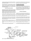
SYSTEM INSTALLATION
GENERAL
If the system is to be filled with water for testing or other purposes
during cold weather and before actual operation, care must be taken
to prevent a down draft entering the boiler or freezing air from contacting
the system. Failure to do so may cause the water in the system to
freeze with resulting damage to the system. Damage due to freezing
is not covered by the warranty.
Good practice requires that all piping, etc., be properly supported.
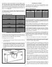
The boilers described in this manual may be used for space (hydronic)
heating or for the heating of potable water. If the heater is to be used for
hydronic space heating, follow the instructions on pages 16-17 given for
equipment required for installation as in Figure 10. However, if units
are to be used for heating potable water, the information describing
specific systems is found on pages 18-20; see Figures 11 and 13.
Installations must comply with all local codes.
INSTALLATION AS BOILER REPLACEMENT
Installation as boiler replacement on an old system with large water