


6
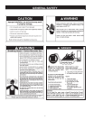
* CAUTION HARNESS HAS 120 VAC. IN OPERATION.
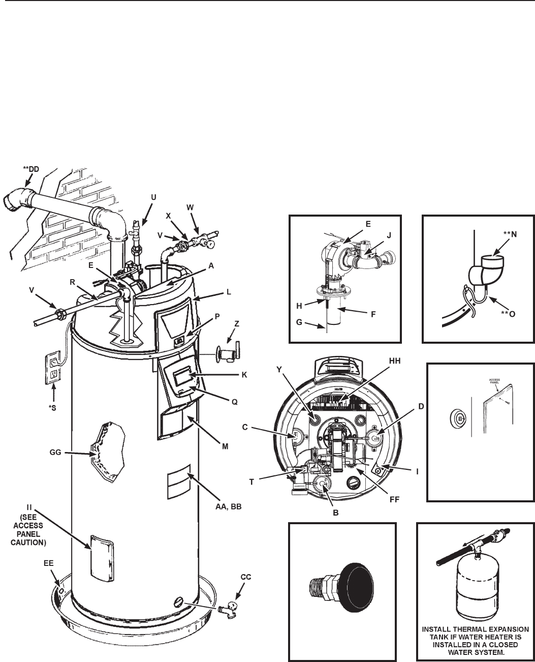
** See “Planning the Vent System,” “Installation of Vent System” and “Condensate” for more information.
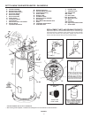
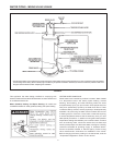
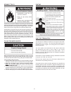
FIGURE 1.
VACUUM RELIEF
VALVE
*INSTALL PER
LOCAL CODES
M Display Enclosure
** N Exhaust Elbow Assembly
** O Condensate Tubing
P Off/On Switch
Q Display Label
R Hot Water Outlet
*S Electrical Outlet (120VAC)
T Gas Supply
U Main Manual Gas Shutoff Valve
V Union
W Inlet Water Shutoff Valve
X Cold Water Inlet
GET TO KNOW YOUR WATER HEATER - GAS MODELS
A Control Assembly
B Blocked Inlet Switch
C Blocked Outlet Switch
D Fan Prover Switch
E Blower Assembly
F Burner Assembly
G Flame Sensor
H Hot Surface Igniter
I Junction Box
J Gas Control Valve Thermostat
K Display Board
L Top Plastic Enclosure
Y Inlet Dip Tube
Z T/P Relief Valve
AA Rating Plate
BB Labels
CC Drain Valve
** DD Vent Terminal
EE Metal Drain Pan
FF Anode
GG Insulation
HH Upper Temperature Probe
II Access Door
REPLACEMENT PARTS AND DELIMING PRODUCTS
Replacementpartsandrecommendeddelimermaybeorderedthrough
authorizedservicersordistributors.Whenorderingparts,providecomplete
modelandserialnumbers(seeratingplate),quantityandnameofpart
desired.Standardhardwareitemsmaybepurchasedlocally.
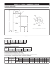
Caution:
Thisaccesspanelcovers
a2”NPTplugthatwasrequired
duringthemanufacturingofthis
waterheater.This2”NPTangeis
not a cleanout tting,removingthe
2”NPTplugandusingthisttingasa
cleanout could void your warranty.
ACCESS PANEL