


28
CONTROLS AND SWITCHES
Thismodelisprovidedwiththreepressureswitches.Theseswitches
areessentialtothesafeandproperoperationoftheunit.Allswitches
arewiredinseries.Thecontrollerissetuptoshuttheunitdown
wheneverthereisafailureofanyoftheswitches.Itisimportantto
understandthepurposeofeachswitch.
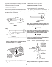
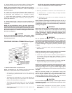
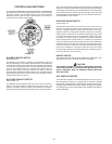
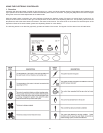
FIGURE 12.
BLOWER PROVER SWITCH
(SEEFIGURE12)
TheBlowerProverSwitchisprovidedontheheatertoverifythat
thefanisoperating.Itisapositivepressureswitchwhoseelectrical
contactsarenormallyopen.Whenthefanincreasesthepressure
intheburner,thepressureswitchwillallowtheelectricalcontacts
toclose.Thepressureswitchisconnectedtotheburnertapbya
pieceoftygontubing.Thistubingmustbeconnectedinorderfor
theswitchtochangetheelectricalcontacts.Thecontrollerrequires
thattheelectricalcontactsonthisairowswitchbeopenbeforeit
willallowtheblowertocomeon.
BLOCKED EXHAUST SWITCH
(SEEFIGURE12)
TheBlockedExhaustSwitchissetuptoshuttheunitoffwhena
build-upofpositivepressureintheexhaustventpipeoccurs.This
switchisapositivepressureswitchthatrequiresanincreasein
pressuretochangetheelectricalcontactsfromnormallyclosedto
open.Whenthisswitchpreventstheunitfromigniting,mostlikelythe
exhaustisblockedbysomemeans.Checktoseeifthecondensate
isallowedtoowfreelyfromtheexhaustelbowandforobstructions
intheexhaustventingandexhaustventterminal.Alsoverifythat
theventlengthdoesnotexceedthemaximumallowedasshownin
theVentSectionofthismanual.
BLOCKED INTAKE SWITCH
(SEEFIGURE12)
TheBlockedIntakeSwitchissetuptoshuttheunitoffwhena
build-upofnegativepressureintheintakeairpipeoccurs.This
switchisanegativepressureswitchthatrequiresanincreasein
negativepressuretochangetheelectricalcontactsfromnormally
closedtoopen.Theswitchisconnectedtothepressuretaponthe
PVCpipeconnectedtotheinletoftheblower.Whenthisswitch
preventstheunitfromigniting,mostlikelytheintakeisblocked.
Verifythatthescreenontheintakeairconnection(conventional
vent),theintakeairpipeandtermination(directventinstallations)
arefreeofobstructionsthatmaypreventairfromenteringtheunit.
Insurethescreenonintakeairconnectionhasbeenremovedon
directventinstallations,seeFigure18B.Alsoverifytheintake
airpipelengthdoesnotexceedthemaximumallowedasshown
intheVentSectionofthismanual.
ON/OFF SWITCH
TheON/OFFSwitchisasingle-pole,single-throwrockerswitch.This
switchprovides120Vfromthelinesourcetotheheater.
CAUTION
THE WATER HEATER IS POLARITY SENSITIVE. BEFORE
APPLYING ELECTRICITY TO THIS HEATER BE CERTAIN THAT
SUPPLY NEUTRAL WIRE TO GROUND CHECK INDICATES
ZERO VOLTAGE.
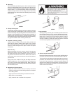
HOT SURFACE IGNITER
TheHotSurfaceIgniterisadevicethatignitesthemainburnerby
hightemperature(>1800°For>982°C).When120VACisapplied
totheigniter,sufcientheatisgeneratedtoignitethemainburner.
Althoughimprovementshavebeenmadetostrengthentheigniter,
itisstillfragileandcaremustbetakenwhenhandlingtheigniterto
preventbreakage.