


20
INSTALLATION OF VENT SYSTEM
Beforebeginninginstallationofpipingsystemthoroughlyread
thesectionofthismanualVENTPIPEPREPARATION.
Ifyouareinstallingyoursystemsothatitventsthroughroof,
pleaserefertosection titledINSTALLATIONOFVERTICAL
VENT SYSTEM.
VENT TERMINAL INSTALLATION, SIDEWALL
1. Installtheventterminalbyusingthecoverplateasatemplate
tomarktheholefortheventpipetopassthroughthewall.
BEWARE OF CONCEALED WIRING AND PIPING INSIDE
THE WALL.
2. IftheVentTerminalisbeinginstalledontheoutsideofa
finishedwall,itmaybeeasiertomarkboththeinsideand
outsidewall.Aligntheholesbydrillingaholethroughthe
centerofthetemplatefromtheinsidethroughtotheoutside.
Thetemplatecannowbepositionedontheoutsidewallusing
thedrilledholeasacenteringpointforthetemplate.
3. A)MASONRYSIDEWALLS
Chiselanopeningapproximatelyonehalfinch(1.3cm)larger
thanthemarkedcircle.
B)WOODENSIDEWALLS
Drillapilotholeapproximatelyonequarterinch(0.64cm)outside
ofthemarkedcircle.Thispilotholeisusedasastartingpoint
forasaws-allorsabresawblade.Cutaroundthemarked
circlestayingapproximatelyonequarterinch(0.64cm)outside
oftheline.(Thiswillallowtheventtoeasilyslidethrough
the opening.The resulting gap willbecoveredupbythe
VentTerminalcoverplate.)Repeatthissteponinsidewallif
necessary.
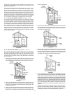
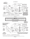
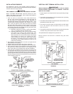
SEQUENCE OF INSTALLATIONS, FIGURE 18A
CutalengthofPVCpipeabout3.5inches(8.9cm)longerthanthe
wallthicknessattheopening.Gluetheventterminaltothis
sectionofpipe.Slidethewallplateoverthepipetostopagainst
theventterminal.Placeabeadofcaulking(notsupplied)around
thegapbetweenthepipeandcoverplate.Applyenoughto
fillsomeofthegapbetweenthepipeandwall.Placesomeof
thecaulkingonthebackoftheplatetoholditagainstthewall
afterinstallation.Iftheventpipeisinstalleduptothewall,with
acouplingontheendagainstthewallopening,thepipewith
theventterminalcanbepreparedforgluingbeforeinserting
throughthewall.Slidethepipethroughthewallandinsert
intothecouplingontheothersideofthewall,makingsurethat
theventterminalendsuppointedinthecorrectposition,see
Figure18A.
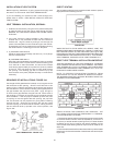
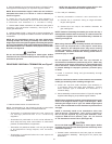
VENT TERMINATION - FIGURE 18A.
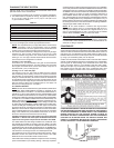
DIRECT VENTING
Theairintakeprovidedontheunitcontainsameshscreentoprevent
largeparticlesfromenteringtheunit.
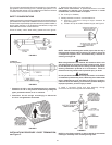
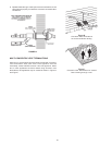
FIGURE 18B.
WHEN THE UNIT IS TO BE SETUP AS A DIRECT VENT, THE
MESH SCREEN MUST BE REMOVED. THE INLET VENT PIPE
MAYTHENBEGLUEDTOTHEAIRINTAKE(SeeFigure18B)
PROVIDED ON THE UNIT. THE SCREEN REMOVED FROM THE
INTAKENEEDSTOBEINSERTEDINTOTHE2”-22.5DEGREE
VENT TERMINAL SUPPLIED IN THE VENT TERMINAL KIT.
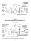
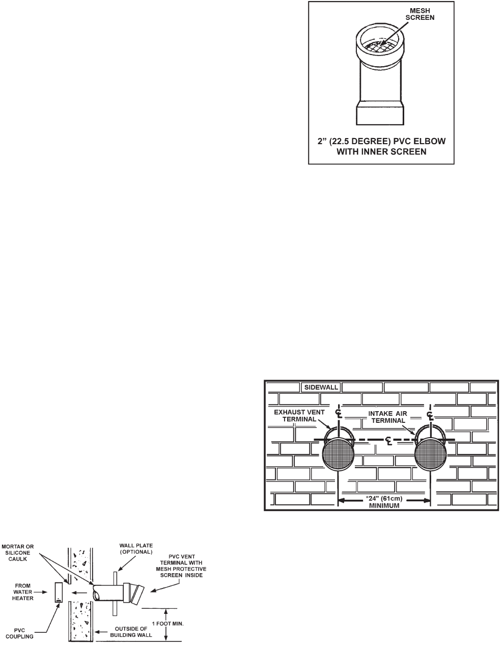
DIRECT VENT TERMINAL INSTALLATION IMPORTANT
THIS UNIT CONSISTS OF TWO VENT TERMINALS - AN INTAKE
VENT TERMINAL AND AN EXHAUST VENT TERMINAL. THE INTAKE
VENTTERMINALISA2”22.5°PVCELBOW(-)WITHAMESHWIRE
SCREENANDTHEEXHAUSTVENTTERMINALISA2”22.5°PVC
ELBOW WITH A MESH WIRE SCREEN.
NOTE: TO PREVENT EXHAUSTING PRODUCTS FROM
CIRCULATINGTOTHEAIRINTAKEINWINDY/COLDAREAS,
THE MAXIMUM PRACTICAL DISTANCE BETWEEN THESE TWO
TERMINALS IS RECOMMENDED.
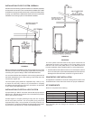
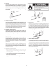
FIGURE 18C.
WHEN LOCATING THE TERMINALS ON A SIDEWALL, THE
FOLLOWING SPECIFICATIONS PERTAINING TO TERMINAL
LOCATION MUST BE FOLLOWED.
1.Theintakeairterminalandtheexhaustventterminalmustterminate
onthesameexteriorwallandmustbeseparatedbyaminimumof
24”(61cm)onverticalcenterline(seeFigure18C).Incolderclimates
increasingthe24”(61cm)minimumwillreducepossibilityoffrost
overfromsidewindsblowingexhaustvaporstotheairintakeofthe
direct vent.
2.Thehorizontalcenterlineoftheintakeairterminalmaynotbelocated
lowerthanthehorizontalcenterlineoftheexhaustventterminal(see
Figure18C).