


21
INSTALLATION SEQUENCE
ForinstallationsintheCityofLosAngeles,CaliforniaCategoryIV
PVCPipesuchasthatmanufacturedbyBrownlinePipeCompany,
mustbeusedasventpipematerial.
CAUTION
VENT TERMINALS SUPPLIED WITH HEATER MUST BE USED.
NOTE: BEFORE BEGINNING INSTALLATION OF ANY
VENT PIPE READ THE VENT PIPE MANUFACTURER’S
INSTALLATION INSTRUCTIONS.
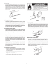
1. Afterthepointsofterminationhavebeendetermined,
usethecoverplatesastemplatestomarktheholesfor
theventpipestobeinsertedthroughthewall.BEWAREOF
CONCEALED WIRING AND PIPING INSIDE OF WALL. If the
ventterminalsarebeinginstalledontheoutsideofanished
wall,itmaybeeasiertomarkboththeinsideandoutside
wall.Aligntheholesbydrillingaholethroughthecenterofthe
templatefromtheinsidethroughtotheoutside.Thetemplate
cannowbepositionedontheoutsidewallusingthedrilledholes
asacenteringpointforthetemplate.
A.) MASONRYSIDEWALLSChiselanopeningapproximately
1/2”(1.3cm)largerthanthemarkedcircle.
B.) WOODENSIDEWALLSDrillapilotholeapproximately
onequarterinchoutsideofthemarkedcircle.This
pilotholeisusedasastartingpointforasaws-allor
sabresawblade.Cutaroundthemarkedcirclestaying
approximatelyonequarterinchoutsideoftheline.
(Thiswillallowtheventpipetoeasilyslidethrough
theopening.Theresultinggapwillbecoveredbythe
ventterminalcoverplates.)Repeatthissteponthe
inside wall if necessary.
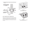
2. Cutalengthof3”PVCpipeabout3.5”(8.9cm)longerthanthe
wallthicknessattheopening.
3. Gluetheintakeventterminaltothesectionofthepipe.
4. Slidethewallplateoverpipetostopagainstintakeventterminal.
5. Placeabeadofcaulking(notsupplied)aroundthegapbetween
thepipeandthewall.Placesomeofthecaulkingonthe
backoftheplatetoholditagainstthewallafterinstallation.
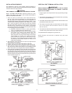
6. Iftheventpipeisinstalleduptothewall,withacouplingonthe
endagainstthewallopening,thepipewiththeventterminalcan
bepreparedforgluingbeforeinsertingthroughthewall.Slidethe
pipethroughthewallandinsertintocouplingontheothersideof
thewall,makingsurethattheventterminalendsuppointedinthe
correctposition(Figure19).
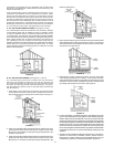
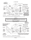
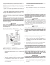
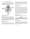
FIGURE 19.
VERTICAL VENT TERMINAL INSTALLATION
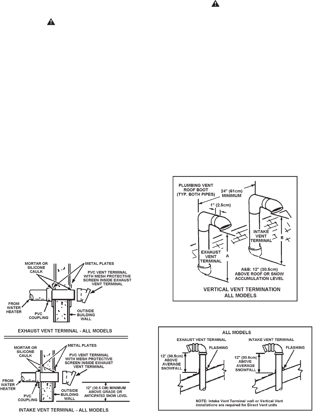
IMPORTANT
WHEN TERMINATING THROUGH A ROOF, THE FOLLOWING
SPECIFICATIONS PERTAINING TO TERMINAL LOCATION
MUST BE FOLLOWED.
1. Propersupportmustbeprovidedforallpipeprotrudingthrough
the roof.
2. Theverticalroofterminationsshouldbesealedwithaplumbing
roofbootorequivalentashing.
3. Theintakeventterminationandtheexhaustventterminationmust
penetratethesamesideofroof.
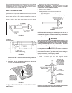
4. Thecenterlineoftheintakeventterminationandthecenter
lineoftheexhaustventterminationmustbenocloser
than24”(61cm).
5. Theintakeventterminalandtheexhaustventterminalmustbe
orientedfacingdownwardandthesamedirection.
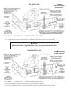
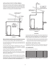
ThespecicationsaredisplayedinFigures20&21.
NOTE:Exhaust ventterminal is installed using the same
procedure.
FIGURE 20.
FIGURE 21.