


32
Temperature Sensors
Overview:
The temperature sensors used in this water heater are
negative temperature co-effi cient (NTC) thermisitors.
With this type sensor, as temperature increases,
the resistance across the thermisitor decreases or
as temperature decreases, resistance will increase.
The control board monitors the resistance of each
sensor and converts each to a corresponding
temperature. There are fi ve (5) such sensors
installed on the heat pump water heater to monitor
ambient, evaporator (coil), upper tank, lower tank and
compressor discharge temperatures. Each is critical
to the operation of the unit. If there is a connection
issue with any sensor, there should be a connection
fault displayed on the User Interface Module (UIM)
Maintenance Display see “Accessing the Maintenance
Display” (p.21).
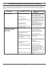
The water heater can continue to heat water with a
faulty temperature sensor, but operation will be affected
as follows:
• The unit can function with a faulty lower tank
temperature sensor. Upper tank temperature will
be used in place of average tank temperature.
• A fault with the ambient, compressor discharge
or coil (evaporator outlet) temperature sensor will
cause a HEAT PUMP fault, locking out the heat
pump. The unit will operate as if in ELECTRIC
mode until the problem is resolved and the fault is
cleared.
• An upper tank temperature sensor fault will lock
out all water heating means, both heat pump and
elements, until the problem is resolved and the
fault is cleared.
NOTE: After the problem is resolved, a fault must
be cleared by turning off power to the unit at the
breaker or fuse panel for ten (10) seconds and
then turning it back on.
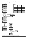
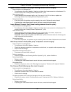
Temperature Sensor Resistance
Measurement:
If a temperature sensor connect fault is indicated by
the Maintenance Display or if a temperature sensor
issue is suspected, use the following procedure to
check the sensor(s):
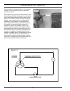
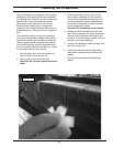
1. Check the resistance of a suspect temperature
sensor by disconnecting the appropriate connector
from the control board and placing the meter leads
on the corresponding connector pins (see Table 4).
Note that there are contacts located on the side of
each connector that should be used.
2. Note the ambient temperature.
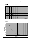
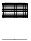
3. Compare the resistance reading on the appropriate
Resistance vs. Temperature graph for the sensor
being checked. If the reading is within ±2% of the
value obtained from the graph, the sensor is good.
If the value is outside this tolerance, the sensor
should be replaced.
A more thorough check of a sensor can be done by
checking at high and low temperature extremes. Check
at low temperature by placing the sensor in ice. The
reading should be 32°F. High temperature can be
checked also, but do not exceed 130°F for the ambient
sensor. All other sensors can be checked up to the
boiling point (212°F). Submerge only the end of the
sensor in boiling water; do not submerge the wire.
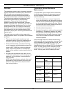
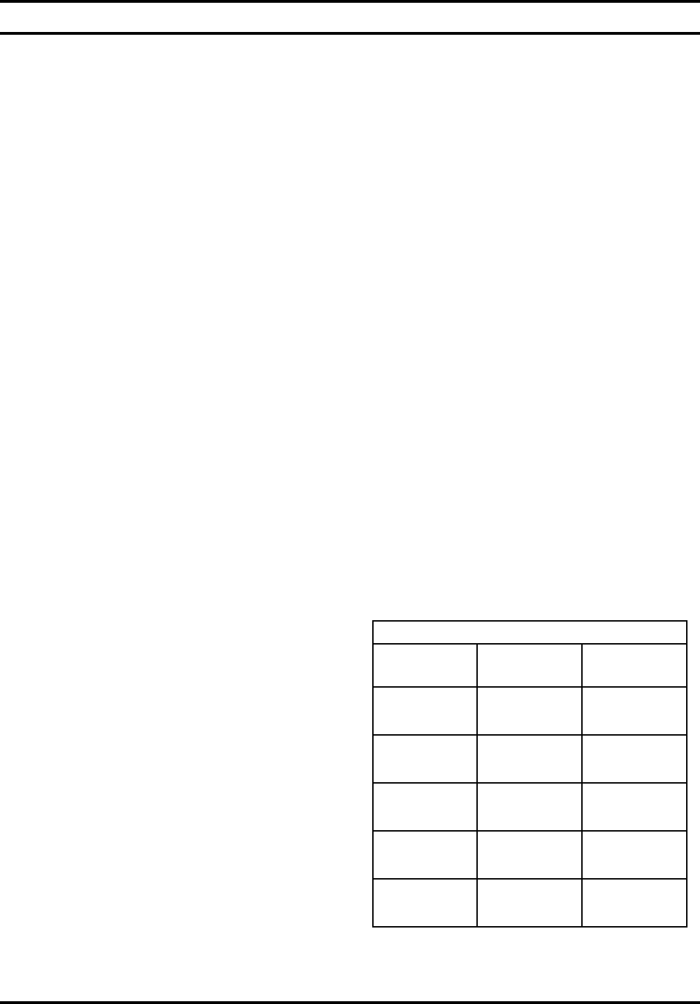
TABLE 5
Sensor Connector /
Pins
Chart
Ambient CN212
Pins 1 to 2
Chart #1
Coil-
Evaporator
CN212
Pins 5 to 6
Chart #1
Tank-Upper CN204
Pins 1 to 2
Chart #2
Tank-Lower CN204
Pins 3 to 4
Chart #2
Discharge-
Compressor
CN212
Pins 3 to 4
Chart #2