


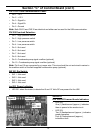

18
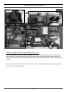
CN 211/215 UIM Communication Cable:
• Pin 1 - +5 V
• Pin 2 - +12 V
• Pin 3 - Signal A+
• Pin 4 - Signal B+
• Pin 5 - Ground
Note: Both CN211 and CN215 are identical and either can be used for the UIM communication.
CN 208 Overload Detection:
• Pin 1 - High pressure switch.
• Pin 2 - High pressure switch.
• Pin 3 - Low pressure switch.
• Pin 4 - Low pressure switch.
• Pin 5 - Not used
• Pin 6 - Not used
• Pin 7 - Not used
• Pin 8 - Not used
• Pin 9 - Condensate pump signal overfl ow (optional)
• Pin 10 - Condensate pump signal overfl ow (optional)
Note: Pin 9 and 10 are connected by a jumper wire. This wire should be cut and wired in series to
the overfl ow switch of the fi eld supplied condensation pump (optional).
SW 201 Dip Switch:
• SW 1 - Not used
• SW 2 - Not used
• SW 3 - Not used
• SW 4 - Not used
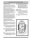
Led 201 Power Indicator:
• LED 201 when illuminated, indicate that 5 and 12 Volts DC are present for the UIM
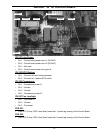
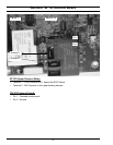
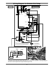
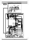
Section D
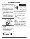
LED 202/203 Powered Anode Indicators:
• LED 202-
One (1) fl ash/second (approx.), indicates
there is power to the anode circuit.
• LED 203-
Two (2) fl ashes/second (approx.), indicates
proper operation.
Four (4) fl ashes/second (approx.),
indicates a fault.
Figure 9
LED
203 / 202
Section D
Section “C” of Control Board (con’t)