


10
tubing so that any discharge from the valve exits only within
6 in. (152mm) above drain, or at any distance below, the
structural fl oor, and does not contact any live electrical part.
The discharge opening must not be blocked or reduced in
size under any circumstance.
IMPORTANT: Only a new temperature and pressure relief
valve should be used with your water heater. Do not use an
old or existing valve as it may be damaged or not adequate
for the working pressure of the new water heater. Do
not place any valve between the relief valve and the
tank.
The Temperature & Pressure Relief Valve:
• Shall not be in contact with any electrical part.
• Shall be connected to an adequate discharge line.
• Shall not be rated higher than the working pres-
sure shown on the data plate of the water heater.
The Discharge Line:
• Shall not be smaller than the pipe size of the relief
valve or have any reducing coupling installed in the
discharge line.
• Shall not be capped, blocked, plugged or contain
any valve between the relief valve and the end of
the discharge line.
• Shall terminate a maximum of 6 in. (152mm) above
a floor drain or external to the building. In cold
climates, it is recommended that the discharge pipe
be terminated at an adequate drain inside the build-
ing.
• Shall be of material listed for hot water distribution.
• Shall be installed to allow complete drainage of
both the valve and discharge line.
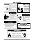
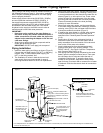
Explosion Hazard
7HPSHUDWXUHSUHVVXUHUHOLHI
YDOYHPXVWFRPSO\ZLWK$16,
=&6$DQG$60(
FRGH
3URSHUO\VL]HGWHPSHUDWXUH
SUHVVXUHUHOLHIYDOYHPXVWEH
LQVWDOOHGLQRSHQLQJSURYLGHG
&DQUHVXOWLQRYHUKHDWLQJ
DQGH[FHVVLYHWDQNSUHVVXUH
&DQFDXVHVHULRXVLQMXU\RU
GHDWK
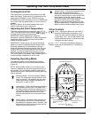
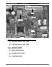
6” (152mm)
Maximum
Air Gap
Drain Pan
2 1/2” (63.5mm)
Depth Maximum and
2” (51mm) wider than
the water heater.
Discharge Pipe
(Do Not Plug or Cap)
Temperature and
Pressure Relief Valve
Drain Line 3/4” (19mm)
ID Minimum
Drain
Figure 3
Temperature and Pressure
Relief Valve Installation
For protection against excessive pressures and
temperatures, a temperature and pressure relief valve must
be installed in the opening marked “T & P RELIEF VALVE”
(Figure 3).
To reduce the risk of excessive pressures and temperatures
in this water heater, install temperature and pressure relief
protective equipment required by local codes, but no less
than a combination temperature and pressure relief valve
certifi ed by a nationally recognized testing laboratory that
maintains periodic inspection of the production of listed
equipment or materials, as meeting the requirements for
Relief Valves and Automatic Shutoff Devices for Hot Water
Supply Systems, ANSI Z21.22 - latest edition. This valve must
be marked with the maximum set pressure not to exceed
the marked maximum working pressure of the water heater.
Install the valve into an opening provided and marked for
this purpose in the water heater, and orient it or provide
Temperature and Pressure Relief Valve
Closed System/Thermal Expansion
As water is heated, it expands (thermal expansion). In
a closed system, the volume of water will grow. As the
volume of water grows, there will be a corresponding
increase in water pressure due to thermal expansion.
Thermal expansion can cause premature tank failure
(leakage). This type of failure is not covered under
the limited warranty. Thermal expansion can also
cause intermittent temperature-pressure relief valve
operation: water discharge from the valve due to
excessive pressure build up. The temperature pressure
relief is not intended for the constant relief of thermal
expansion. This condition is not covered under the
limited warranty.
A properly-sized thermal expansion tank should be
installed on all closed systems to control the harmful
effects of thermal expansion. Contact a plumbing
service agency or your retail supplier reguarding the
installation of a thermal expansion tank.