


27
Powered Anode Troubleshooting and Replacement
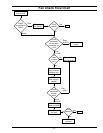
Checking the Powered Anode for Proper
Operation:
When dissimilar metals are in contact with water, a
galvanic cell will likely result and corrosion of the metal
components will occur. If left unchecked, corrosion
will weaken the wall of a water heater tank which will
eventually leak. Passive anodes are typically used to
counteract this corrosion and extend tank life. Passive
anodes erode over time and become less effective
until they stop working all together, another type of
protective device is a powered anode.
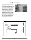
A powered anode is an active device that counteracts
galvanic corrosion in the water heater tank. Unlike
a standard depleting anode, a powered anode does
not lose effectiveness over time. The powered anode
circuit is made up of an electronic control, a titanium
anode rod, and the water heater tank. The electronic
control monitors conditions in the tank and produces
a voltage that will prevent galvanic corrosion from
occuring. The titanium anode rod consists of two
functional parts: A steel body which threads into the
tank providing mechanical and electrical connection to
the tank and a titanium rod that is electrically insulated
from the body. The voltage produced by the powered
anode circuit is delivered to the titanium anode rod by
a red wire connected to the tab that connects to the
anode rod. Current fl ows from the titanium anode rod,
through the water and to the grounded tank wall. The
powered anode circuitry will maintain the minimum
voltage required to protect the tank steel.
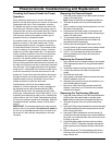
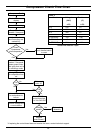
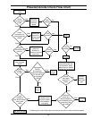
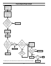
Fault detection is built into the powered anode
software. If a fault is detected, an error message will
be displayed on the User Interface Module (UIM):
“Powered Anode Fault”. By checking the fault code
history see “Interpreting the Fault Code History” (p.21),
a specifi c fault code can be read to aid in isolating the
cause. Refer to the Fault Code Troubleshooting guide
for the list of powered anode fault messages, what the
messages indicate, possible causes, and corrective
actions.
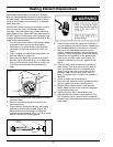
IMPORTANT: The anode protecting the tank requires
power to the unit to operate. Do not shut off power to
the unit for an extended period of time. If power must
be turned off, drain the tank completely to minimize
corrosion.
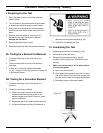
Removing the Powered Anode:
1. Press the power button on the UIM to place the water
heater in Standby Mode.
Note: Power to the board is still present at this time.
2. Terminate all power to the unit at the breaker/fuse
panel.
3. Open a nearby hot water faucet and allow to run until
the water is no longer hot.
4. De-pressurize the water heater by closing the cold
water supply valve to the water heater and opening a
nearby hot water faucet.
5. The powered anode is located on the left side of
the heat pump compartment and is between the
compressor and the evaporator.
6. Remove the top housing see “Removing the Top
Housing” below to gain access to the powered anode.
7. Un-plug the red wire from the powered anode.
8. Use a 1-1/16 inch deep well socket with extension
and long breaker bar to loosen and remove the
powered anode.
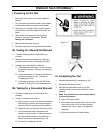
Replacing the Powered Anode:
1. Apply a small amount of thread sealant to the threads
of the replacement anode. Do not get thread sealant
on anode.
2. Thread the anode into the spud and torque to 50 lb-ft.
3. Connect the red wire to the tab on the powered
anode.
4. Re-fi ll the tank with water.
5. Apply power to the water heater and press the power
button if needed to turn it on.
6. Wait eight (8) minutes for the dry fi re detection to run
and for water heating to begin.
7. Monitor the UIM to see if the powered anode fault
repeats. It may take up to 70 minutes for a powered
anode fault to appear.
Removing the Top Housing (Shroud):
1. Press the power button on the User Interface Module
(UIM) to place the water heater in standby mode.
Note: Power to the board is still present at this time.
2. Terminate all power to the unit at the breaker/fuse
panel.
3. Using a #2 Phillips head screwdriver, remove the eight
(8) screws attaching the left louvered panel to the top
of the unit and set aside.
4. Using a #2 Phillips screwdriver, remove the two (2)
screws from the control board cover located inside the
top of the unit on the right side, then remove the cover
by lifting up and out.
5. Locate the ribbon cable and disconnect from either
CN211 or CN215. Thread the connector through the
plastic grommet on the bottom left side of the control
box.
6. Remove the seven (7) screws attaching the shroud
to the top of the unit and carefully lift the top up and
away from the unit.