


PRE SERVICE CHECKS
Servicing should only be performed by a Qualified Service Agent
6
PRE SERVICE CHECKS
WIRING CONNECTIONS
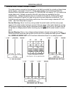
With the power supply to the water heater turned off ensure the wiring connections are
properly tightened to all components including: high voltage terminal blocks, fuse blocks,
contactors, transformers and heating elements.
Loose connections at any connection point will cause increased amperage and excessive
heat which can damage wiring and components. Whenever worn or damaged wiring and
components must be replaced ensure all wiring connections are properly tightened before
putting the water heater back in service.
SERVICE PRECAUTIONS
1 DO NOT energize the branch circuit supplying power to the water heater or test the
water heater electrical system before the water heater is completely filled with water.
Read the start up procedures in the Instruction Manual that came with the water heater.
2 Be sure to turn off power and use a lock out device at the branch circuit power supply
disconnect switch or breaker when servicing the electrical system of the water heater.
Never touch electrical components with wet hands or when standing in water.
3 When replacing heating elements ensure they are rated at the correct voltage and KW
for the water heater being serviced - see Heating Element Ratings and Heating Element
Configurations on page 21 and Replacing Heating Elements on page 26.
4 When replacing fuses use an insulated fuse puller to remove and install fuses. Always
use the correct size for the circuit. See the Replacement Fuses Service Note on page 17
in this manual.
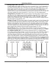
5 Using an AC volt meter measure the branch circuit power supply voltage to the water
heater. Ensure the measured voltage of the branch circuit supplying power to the water
heater matches the water heater’s rating label - see pages 12 - 14.
6 Ensure the internal power phase configuration matches the power supply to the water
heater. The water heaters covered by this manual are phase convertible - see pages 15
and 16.
7 Electronic Control Models covered by this manual are equipped with contactors and will
have a multi tap control circuit transformer. This is a step down transformer that outputs
120 VAC (secondary winding) which is used to power the electronic control system and
energize the contactor coils. The transformer can accommodate different power supply
voltages and has multiple input voltage connections or “taps.” Ensure the input supply
voltage (primary winding) wiring to the transformer is connected properly. See page 34 in
this manual.
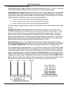
Service Note - Contactor Chatter: Incorrect supply voltage wiring to the multiple tap 120
VAC Control Circuit Transformer on Electronic Control Models will cause low/high output
voltage from the transformer. This can cause contactors to open and close their contacts
rapidly (contactor chatter) and result in permanent damage to the contactors. Ensure the
primary winding of the multiple tap 120 VAC Control Circuit Transformer is wired to match
the power supply voltage - see pages 12 -14 and page 34.