


Servicing should only be performed by a Qualified Service Agent
43
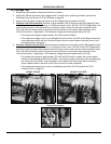
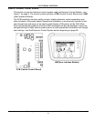
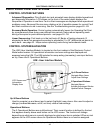
ELECTRONIC CONTROLS
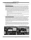
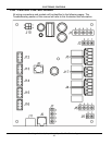
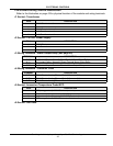
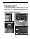
CCB Socket & Wiring Terminal Identification
Refer to the illustration on page 42 for physical location of the sockets and wiring terminals.
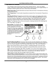
J1 Socket - Transformer
J2 Socket - 120 VAC Power Supply
J3 Wiring Terminals - Alarm Output Relay (see page 59)
J4 Wiring Terminals - Contactor Coils
J5 Socket - Immersion Temperature Probe/ECO
J6 Socket - Not Used
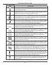
PIN # DESCRIPTION
1 120 VAC hot to transformer
2 Not used
3 120 VAC neutral to transformer
4 24 VAC out from transformer
5 24 VAC out from transformer
PIN # DESCRIPTION
1 120 VAC hot
2 Earth Ground
3 120 VAC neutral
TERMINAL DESCRIPTION
N. O. Dry Contact Output - Normally Open Terminal Alarm Output Relay
N. C. Dry Contact Output - Normally Closed Terminal Alarm Output Relay
COM Dry Contact Output - Common Terminal Alarm Output Relay
TERMINAL DESCRIPTION
OUT 1 120 VAC hot to Heating Element Bank 1 Contactor Coils
OUT 2 120 VAC hot to Heating Element Bank 2 Contactor Coils
OUT 3 120 VAC hot to Heating Element Bank 3 Contactor Coils
PIN # DESCRIPTION
1 ECO (energy cut out) 120 VAC hot out (red wire)
2 Temperature probe (thermistor) +5.0 VDC (black wire)
3 Temperature probe (thermistor) -5.0 VDC (black wire)
4 ECO (energy cut out) 120 VAC return (red wire)