


Servicing should only be performed by a Qualified Service Agent
33
OPERATION & SERVICE
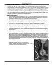
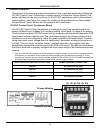
Contactor Coil Voltage - At CCB
This test procedure will measure contactor coil voltage where it originates at the J4 wiring
terminals on the CCB. See page 42 for the CCB’s J4 wiring terminal location.
1 Ensure tank temperature is less than 100°F/38°C - dump water to lower tank temperature if necessary.
2 Adjust the temperature settings to ensure a call heat is active for all heating elements. Raise the Operating
Set Point in the Temperatures Menu to 140°F or higher. Set all Heating Element Bank Differentials in the
Temperatures Menu to 2°F - see pages 52 and 53.
3 Using an AC volt meter; set the volt meter to an AC voltage range just above 120 VAC.
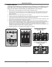
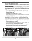
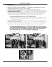
4 Touch one of the two volt meter probes to the ground wire connection on the water heater. Touch the other
volt meter probe to the CCB’s J4 OUT 1 wiring terminal. See the images below. On water heaters
equipped with 6 or 9 heating elements also check between the ground connection and the CCB’s J4 OUT
2 wiring terminal and on water heaters equipped with 9 elements also check between ground and the
CCB’s J4 OUT 3 wiring terminal. Measure and record voltage readings taken in this Step.
Service Warning: Be extremely careful when performing this test procedure - there will be high voltage
present at many terminals and wiring connections in the surrounding area.
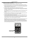
5 If the measured voltage(s) were approximately 120 volts the CCB circuit board is operating properly.
6 If the measured voltage(s) were zero or considerably less than 120 volts call the toll free Technical Support
phone number listed on the back cover of this manual for further assistance.
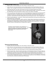
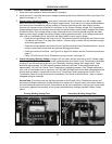
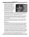
Checking Contactor Coil Voltage at the CCB’s J4 Wiring Terminals
Water Heater Ground and J4 OUT 1 Water Heater Ground Connection CCB’s J4 OUT 1 Terminal