


Servicing should only be performed by a Qualified Service Agent
65
TROUBLESHOOTING
ELECTRONIC CONTROL MODELS
The remainder of the Troubleshooting section covers Electronic Control Models only.
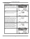
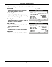
Fault Conditions
When the control system declares a Fault condition it will display a Fault message on the
UIM and lock out. Voltage to the contactor coils and heating elements is terminated to
prevent further heating operation.
Alert Conditions
When the control system declares an Alert condition it will continue heating but will display
an Alert message on the UIM notifying the user that the water heater requires servicing.
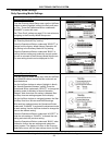
Resetting Control System
Turn the power supply to the water heater off for approximately 20 seconds and then back
on. If the operational problem that caused the control system to declare a Fault or Alert
condition has not been corrected the control system will continue to display the Alert or Fault
message and lock out.
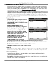
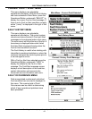
CONTROL SYSTEM UNRESPONSIVE
DISPLAYED MESSAGE
CONDITION/INDICATES
CHECK/REPAIR
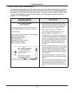
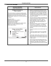
UIM Display Is Blank
UIM is not energized - LCD display is blank.
Possible Causes:
No power to water heater
Blown control circuit transformer fuses
120 VAC power problems
24 VAC power problems
Defective transformer(s)
Wiring or plug/socket connection problems
UIM communication cable problems
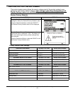
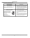
Important Service Reminder:
When performing any troubleshooting steps outlined
in this service manual always consider the wiring
and connectors between components. Perform a
close visual inspection of all wiring and connectors
to a given component before replacement.
Ensure wires were stripped before being crimped in
a wire connector, ensure wires are crimped tightly in
their connectors. Ensure pins inside plugs/sockets
are not damaged or worn, ensure plugs/sockets are
mating properly & providing good contact.
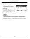
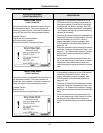
• Check/restore power supply to the water heater
at Power Distribution Block - see pages 12 - 14.
• Check control circuit transformer fuses see Fig-
ure 2 page 9 and checking fuses page 17.
• Check communication cable connections at
UIM’s J2 Socket (page 47) and the CCB’s J11
Port (page 42).
• Install a new communication cable between
UIM’s J2 Socket and the CCB’s J11 Port - use
standard Cat 5 network cable.
• Closely inspect communication ports on CCB
and UIM ensure they are mating properly and
providing good contact (pages 42 & 47).
• Ensure 120 VAC power/ground is supplied to
CCB’s J2 Socket; follow procedure on page 46.
• Check J1 and J2 plug/socket connections on
the CCB - ensure they are mating properly and
providing good contact (page 42).
• Check 24 VAC transformer: follow procedure
outlined on page 36.
• Call the technical support phone number on the
back cover of this manual for further assistance
if the problem has not been corrected after per-
forming the procedure outlined here.