


Servicing should only be performed by a Qualified Service Agent
35
OPERATION & SERVICE
120 VAC Control Circuit Transformer Test
1 Ensure the main breaker or disconnect switch is turned on.
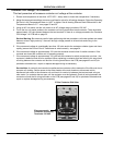
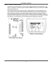
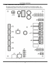
2 Verify with an AC volt meter that proper voltage is present at the Power Distribution Block (see Figure 2 on
page 9 and pages 12 - 14).
3
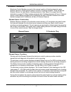
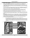
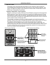
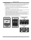
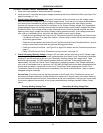
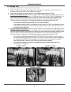
Check Primary Winding Voltage: Using an AC volt meter; set the volt meter to an AC voltage range
above the expected voltage (600 VAC or higher range initially). Touch the two volt meter probes between
the control circuit transformer’s primary winding H1 common terminal and the other primary winding
terminal with a power wired connected to it as shown in the “Primary Winding Voltage Test” image below.
Voltage between these two terminals should match the water heater’s power supply voltage at the Power
Distribution Block. If the voltage at the primary winding terminals of the transformer matches the water
heater’s power supply voltage the primary winding is being powered correctly. If the voltage measured is
zero volts or considerably less or more than the water heater’s power supply voltage:
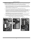
• Check the wiring between the Control Circuit Transformer’s primary winding and the Control Circuit
Fuse Block see Figure 2 on page 9 for location - ensure wiring is correct and connections are tight
and making good contact.
• Check the wiring between the Control Circuit Fuse Block and the Power Distribution Block - ensure
wiring is correct and connections are tight and making good contact.
• Check the control circuit fuses - see Figure 2 on page 9 for location and the Fuse test procedure on
page 17.
• Verify 120 VAC Control Circuit Transformer wiring is correct - see page 34.
4
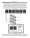
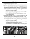
Check Secondary Winding Voltage: Using an AC volt meter; set the volt meter to an AC voltage range
just above 120 VAC. Touch the two volt meter probes between the Control Circuit Transformer’s secondary
winding X1 and X2 terminals as shown in the “Secondary Winding Voltage Test” image below. There
should be approximately 120 VAC present between these two terminals. If the voltage measured is
approximately 120 VAC the Control Circuit Transformer is operating properly. If the voltage measured is
zero volts or considerably less or more than 120 VAC AND all Steps above have been completed and the
results were successful - replace the Control Circuit Transformer. When replacing the Control Circuit
Transformer check all wiring to and from the transformer for pinched or shorted wires - repair or replace
damaged wiring as necessary.
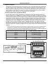
Service Note: A continuity test can also be performed on the Control Circuit Transformer primary and
secondary windings to determine if either winding is an open circuit. Secure power to the water heater at
the main breaker or disconnect switch, Disconnect all wiring to the transformer. Using an ohm meter check
for continuity between the terminals on the primary and secondary windings checked in Steps 3 and 4
above.
Primary Winding Voltage Test Secondary Winding Voltage Test