


Servicing should only be performed by a Qualified Service Agent
45
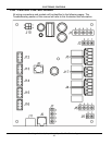
ELECTRONIC CONTROLS
CCB Enable/Disable Circuit(s) Test
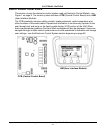
The electronic control system includes two enable/disable circuits (see page 54) for use with
field installed supervisory controls such as building EMS (Energy Management System).
These two circuits are located at the CCB’s four pin J7 Socket. Both of these Enable/Disable
circuits must be closed to enable heating operation. If either circuit is open for any reason
heating operation will be disabled even though the tank temperature may be well below the
Operating Set Point - see Heating Cycle Disabled on page 66.
There is a plug with two jumper wires installed from the factory in the CCB J7 socket to
enable heating operation when external controls are not in use. If the plug is not present or if
one of the two jumper wires fails to close either enable/disable circuit heating operation will
be disabled. A simple continuity check is performed on the J7 Plug end to ensure heating
should not be disabled as follows:
1 If either enable/disable circuit is in use (external wiring connected to J7 plug) by an external supervisory
control - ensure that control’s dry contacts are closed to enable heating operation. Check the supervisory
control’s settings/programming to ensure it is not disabling heating operation during occupied/normal
demand periods.
2 If the J7 plug is missing or jumper wires are not installed in the J7 plug - call the toll free Technical Support
phone number listed on the back cover of this manual for further assistance
3 If there are no external supervisory controls wired to the J7 plug: Secure power to the water heater. Unplug
the J7 plug from the CCB circuit board - see page 42 for location.
4 Using an ohm meter; set the Ohm meter to it’s lowest resistance range (< 200) or to an audible beep
continuity test setting if so equipped.
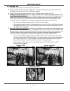
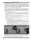
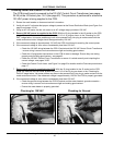
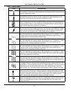
5 Touch the ohm meter probes between pins 1 & 2 first and then between pins 3 & 4 of the J7 plug end as
shown in the images below. There should be continuity present in both tests.
• If the ohm meter shows no continuity (open circuit) between pins 1 & 2 or between pins 3 & 4 of the
J7 plug end ensure the two jumper wires are properly installed in the plug end and are not broken.
Ensure the J7 plug/socket connection is mating properly and providing good contact. Repair/replace
damaged plug connectors/wiring as necessary.
• If the ohm meter shows continuity (closed circuit) between pins 1 & 2 and between pins 3 & 4 of the
J7 plug end and heating operation will not activate with a cold tank of water call the toll free
Technical Support phone number listed on the back cover of this manual for further assistance.
Service Note: If a supervisory control(s) is used to enable/disable heating operation, install
field wiring between the J7 socket on the CCB and a set of “dry contacts” on the external
control per all applicable building codes. This is a switching circuit only: DO NOT apply any
external voltage or connect any load (IE: relay coil) to either circuit.