


ELECTRONIC CONTROL SYSTEM
Servicing should only be performed by a Qualified Service Agent
54
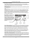
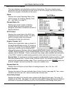
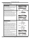
HEATER STATUS MENU
This menu displays non adjustable operational information. This menu contains more
information that can be displayed on one screen of the LCD display. Use the Up & Down
Buttons to navigate to the bottom of this menu.
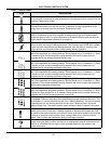
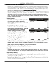
Status
Displays the current Operating State of the
control system. IE: Heating, Standby, Fault
etc. - see Table 2 on page 51.
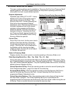
Element Banks On
Displays the current number of heating
element Banks the control system has
energized. Each Bank of elements contains 3
heating elements.
ECO Contact
Displays the current state of the ECO high
temperature limit switch contacts. The ECO
switch is located inside the immersion
Temperature Probe (two red wires).
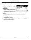
Enable / Disable 1 & 2
Displays the current state, open or closed, of
the two Enable/Disable circuits (J7 socket on
the CCB - see page 42) provided for external
supervisory controls such as building EMS
(Energy Management System). Both of these Enable/Disable circuits must be closed to
“enable” heating operation. If either Enable/Disable circuit is open for any reason heating
operation will be “disabled.” There is a plug with two jumper wires installed from the factory
in the CCB J7 socket to enable heating operation when external controls are not in use.
Service Note: If a supervisory control(s) is used to enable/disable heating operation, install
field wiring between the J7 socket on the CCB and a set of “dry contacts” on the external
control per all applicable building codes. This is a switching circuit only: DO NOT
apply any
external voltage or connect any load (IE: relay coil) to either circuit.
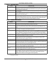
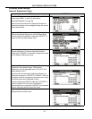
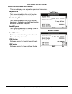
Element Bank On
Displays the on/off status of each Bank of heating elements. Yes = On, No = Off.
Alarm Condition
Displays the status of the user definable Alarm Output function (see page 59). Yes = alarm
condition has been met, No = alarm condition has not been met.
Alarm Relay Output
Displays the state of the normally open contacts of the Alarm Output relay. This relay (J3
contacts on the CCB - see page x?) is used for building EMS (Energy Management System)
notification of operational conditions such as Fault conditions and heating mode status.
Top Of Menu
Bottom Of Menu