


40 www.americanwaterheater.com
Water Circulation Pump
A circulation pump is integrated into the heat engine for
the Hybrid application. The pump serves to push water
through the heat engine at a rate that supports optimum
recovery time and maximum heat output.
The control provides 120Vac, 60Hz line power to the pump
to enable operation.
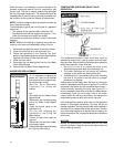
Water Flow Measurement
1. Water Flow Sensor
The Water Flow Sensor uses a sensor for the
detection of the water fl ow. When water fl ows, the
sensor rotates and a transistor is switched on and
off, producing a pulsing signal with a frequency
related to fl ow rate.
2. Water Flow Detection
Flow detection is an on/off indication of whether
there is suffi cient fl ow through the heat exchanger
for normal heating.
3. If the water is less than 0.58 gal/min (2.2 l/min) the
unit stops and will start again when the fl ow is above
0.78 gal/min (2.7 l/min).
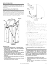
Water Flow Restriction Valve
A motorized valve is placed in series with the circulation
pump and the heat exchanger of the heat engine. This
valve serves to limit the amount of fl ow through the heat
engine such that a variable rate of fl ow can be achieved
from the fi xed-speed pump.
Gas Delivery Safety String
The release of gas into the combustion chamber is of
critical importance to the safe operation of the heater.
The control is a combination of hardware and software
that measure and ensure the gas is released only when
appropriate for combustion. The term “safety string” applies
to those devices or components that directly control the
power applied to the gas valves as well as the gas valves
themselves. The components are:
• main gas valve solenoid,
• stage 1 and 2 gas valve solenoids,
• exhaust vent high temperature switch,
• energy cut out (ECO) temperature switch.
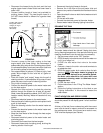
Exhaust Vent High Temperature Switch
The water heater is designed for plastic vent piping typically
used in high effi ciency appliances. To ensure the water
heater will not release exhaust gasses at temperatures that
would cause the vent piping to melt, a bimetallic switch is
mounted on the assembly. The switch used is a normally-
closed switch which will open when the temperature
reaches the maximum design temperature for the venting
used. This switch should reset to the closed position when
the vent pipe temperature cools suffi ciently.
• Opening Temperature is approximately 165°F (74°C)
+/- 5°F (2.8°C).
• Closing Temperature is approximately 135°F (57°C)
+/- 5°F (2.8°C).
The power for the main gas valve is to be routed through
the Exhaust Vent High Temperature Switch causing the
main gas valve to be de-energized immediately when the
switch opens.
The status of the Exhaust Vent High Temperature switch
should be continually monitored by the controller. If an
open switch is detected, the control should declare a
fault and respond according to the fault. The fault is a
continuous lockout.
Energy Cut Out (ECO) Temperature Switch
The heat exchanger of the heat engine is equipped with a
surface-mounted bimetallic switch which opens when the
water temperature exceeds the safe operating temperature
for the water heater.
• Opening Temperature is 185°F +/-9°F (85°C +/-5°C)
• Closing Temperature is 149°F +/-6°F (65°C +/-3°C)
The power from the main gas valve is to be routed
through the ECO switch causing the main gas valve to be
immediately de-energized when the switch opens.
The status of the ECO switch should be continually
monitored by the controller. If an open switch is detected,
the control should declare a fault and respond according
to the fault. This will be a continuous lockout.
Blocked (Exhaust Gas) Outlet Detection
If the exhaust air passage is obstructed, the control is to
enter a fault state and initiate a controlled shut down. This
is an overall safety feature of the control system.
Igniter
The control has an integrated direct spark ignition, which
can turn on, by means of a relay. This feature is integrated
onto the controller board.
By default, the control will allow for three ignition retries
after a failed ignition.
Flame Sensor
An active fl ame is sensed through a fl ame rod located in
the burner assembly in the region of the burners fl ame.
The fl ame sense input will be monitored by the control and
respond to the presence of the fl ame.
Combustion Chamber Temperature Protection
(Thermal Fuse)
If in any conditions when the temperature increases over
287.6°F (142°C) the High Limit Temperature Fuse melts.
This function disconnects the power supply controller, and
must be replaced.