


www.americanwaterheater.com 23
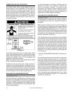
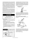
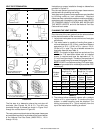
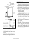
VENT PIPE TERMINATION
STREET ELBOW NORMAL ELBOW
PREFERRED PRACTICE:
90° LONG SWEEP ELBOW
(LESS RESTRICTIVE)
BACK TO BACK ELBOWS
90° SHORT SWEEP ELBOW
(MORE RESTRICTIVE)
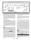
6 in.
(15 cm) min.
NOT RECOMMENDED:
FIGURE 19
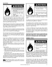
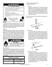
VENT LENGTH LESS THAN OR
EQUAL TO 20 EQUIVALENT FEET
(6.1m) USE THIS SCREEN.
VENT LENGTH GREATER THAN 20
EQUIVALENT FEET (6.1m) USE THIS
SCREEN.
FIGURE 20
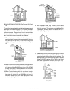
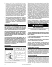
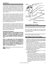
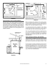
The fi rst step is to determine where the vent pipe will
terminate (see Figures 24, 29 & 31). The vent may
terminate through a sidewall as shown in Figure 24 or
through the roof as shown in Figure 29.
The vent system must terminate so that proper clearances
are maintained as cited in local codes or the current edition
of the National Fuel Gas Code, (ANSI Z223.1, 12.9.1
through 12.9.4).
Instructions on proper installation through a sidewall are
provided in Figures 31.
Plan the vent system layout so that proper clearances are
maintained from plumbing and wiring.
Vent pipes serving power vented appliances are classifi ed
by building codes as “vent connectors”. Required
clearances from combustible materials must be provided in
accordance with information in this manual under FACTS
TO CONSIDER ABOUT LOCATION AND INSTALLING
THE WATER HEATER, and with the National Fuel Gas
Code and local codes.
PLANNING THE VENT SYSTEM
Plan the route of the vent system from the exhaust elbow
to the planned location of the vent terminal.
1. Layout total vent system to use a minimum of vent pipe
and elbows.
2. This water heater is capable of venting fl ue gases a
minimum distance of 10 ft. (0.3m), a maximum distance
equivalent to 50 ft. (15.2m) of 2 in. pipe or 100 ft.
(30.5m) of 3 in. pipe. The use of elbows reduces the
maximum distance (see Table 1).
NOTE: The lengths of pipe listed are exclusive of the
termination. The termination elbow, with an installed
screen, is required and uses the equivalent of 7 ft.
(2.1m) of vent pipe length. Therefore, the remainder of
the vent system must not exceed the lengths listed.
NOTE: Do NOT use Cellcore venting (PVC outer layer,
foamcore-type material for middle layer, and then PVC
inside layer).
Number
of 90°
Elbows
Maximum vent
length for 2 in. pipe
ft. (m)
Maximum vent
length for 3 in. pipe
ft. (m)
Short
Radius
Elbow
Long
Radius
Elbow
Short
Radius
Elbow
Long
Radius
Elbow
1 43 (13.1) 45 (13.7) 93 (28.4) 95 (28.9)
2 36 (10.9) 40 (12.2) 86 (26.2) 90 (27.4)
3 29 (8.8) 35 (10.6) 79 (24.0) 85 (25.9)
4 22 (6.7) 30 (9.1) 72 (21.9) 80 (24.4)
5 15 (4.5) 25 (7.6) 65 (19.8) 75 (22.8)
TABLE 1
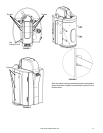
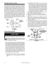
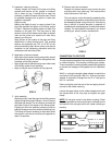
3. The exhaust elbow assembly comes with a straight
section of 2 in. pipe installed. To continue the vent
system, a rubber coupling must be attached. The
venting must extend 6 in. (15cm) vertically from the
top of the heater before installing an elbow.