


32 www.americanwaterheater.com
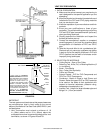
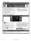
ELECTRICAL CONNECTIONS
The water heater must be connected to a properly
grounded electrical branch circuit. A dedicated circuit is
preferred. Do not use a GFI outlet.
Refer to the rating plate attached to the water heater to
determine the electrical requirements for the heater. Ensure
the circuit provided is correct for these requirements.
Important: Do not use an extension cord to connect the
water heater to an electrical outlet.
Important: The electrical controls used inside the gas
control of this water heater are polarity sensitive. Ensure
the electrical supply is connected correctly in the receptacle
box. Failure to connect correctly will prevent the unit from
functioning properly.
When all the water, gas and venting connections have
been correctly made, fi ll the tank as directed in the section
“FILLING THE WATER HEATER”.
When the tank has been fi lled, connect the electrical power
and proceed with starting the water heater as directed in
the “CALIBRATION” section.
CALIBRATION
The water heater must be calibrated as follows before
being put into service. The Calibration Procedure
examines and measures certain details of your installation
and automatically sets some control parameters. Before
starting the Calibration Procedure, the heater must be
properly installed and connected to the water piping and
the vent system. Ensure all panels, covers and doors are
in place.
Important: To avoid a possible “end of call-for-heat” (and
consequent interruption of the Calibration Procedure), a
continuous water draw from the heater is recommended
during the calibration.
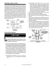
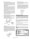
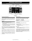
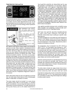
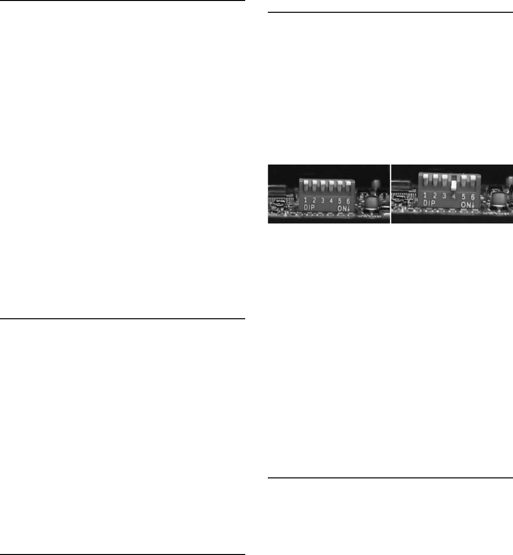
This procedure assumes that the heater is installed with
DIP switch 4 in the calibration (ON or “down”) position
(see Figure 33a).
To calibrate the heater:
Plug the power cord into a 120Vac/60Hz outlet.
Press the Standby Button to turn on the heater and
initiate the Calibration Procedure.
The Calibration Procedure will last about 6 minutes. Do
not interrupt this procedure once it has started. After a
successful calibration the heater will go into standby
mode. During the calibration if the “call-for-heat” ends,
the calibration was not completed and the E36 error
message will be shown on the display. If this occurs,
unplug the power cord and repeat steps 1 and 2.
1.
2.
3.
To put the heater into service after a successful
calibration:
Unplug the power cord from the 120Vac/60Hz outlet
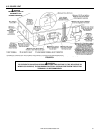
Open (plastic) front door of the heater and remove the
service cap of the heat engine. The DIP switches are
located on the PCB which is mounted on the right-hand
side of the heat engine.
Set DIP switch 4 in the normal (OFF or “up”) position
(see Figure 33a).
Reinstall the front cover of the heat engine, close and
latch the front door of the heater.
Plug the power cord into the 120Vac/60Hz outlet.
Press the Standby Button to turn on the heater and
start the unit.
DIP Switch 4 in
normal mode
(“OFF”, “up”)
DIP Switch 4 in
calibration mode
(“ON”, “down”)
FIGURE 33a
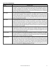
The E36 “calibration error” occurs in the following
situations:
• Calibration switch (DIP switch 4) is in the calibrate (ON
or “down”) position and an “end call-for-heat” occurs
before the Calibration Procedure is fi nished.
• Calibration switch (DIP switch 4) is in the calibrate (ON
or “down”) position there is no “call-for-heat” within 6
minutes of turning on the power.
• Calibration switch (DIP switch 4) is in the calibrate (ON
or “down”) position and the unit is calibrated but the DIP
switch is not set to the normal (OFF or “up”) within 6
minutes after the Calibration Procedure is fi nished.
• Calibration switch (DIP switch 4) is in the normal (OFF
or “up”) position and the unit is not calibrated and 1
minute (or more) passes after turning on the power.
If an E36 error message is displayed:
Unplug the power cord from 120Vac/60Hz outlet.
Open front door of the heater and remove the front
cover of the heat engine.
Check that (or set) DIP switch 4 is in the calibrate (ON
or “down”) position.
Generate a 5 minute (minimum) water draw from the
heater.
Repeat the calibration procedure.
NOTE: If changes are made to the vent system or the
heater is re-located, the Calibration Procedure must be
repeated.
1.
2.
3.
4.
5.
6.
1.
2.
3.
4.
5.