


14 www.americanwaterheater.com
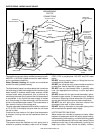
When installing the heater, consideration must be given to
proper location. Location selected should be as close to
the wall as practicable and as centralized with the water
piping system as possible.
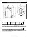
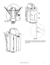
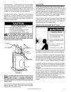
FIGURE 5
Minimum clearances between the water heater and
combustible construction are 0 in. at the sides and rear,
0 in. (0cm) from the front and 2 in. (5.08cm) from the top
(see Figure 5). If clearances stated on the heater differ
from these distances, install water heater according to
clearances stated on the heater.
Adequate top clearance of 24 in. (61cm) for servicing this
appliance, such as changing the anodes etc., should be
considered before installation.
A minimum front clearance of 20 in. (51cm) and 10 in.
(26cm) of side clearance must be allowed for access to
replaceable parts.
EARTHQUAKE ZONES
In Earthquake Zones the water heater must be braced,
anchored, or strapped to avoid moving during an
earthquake. Contact local utilities for code requirements in
your area. The Spacemaker® TSE25 Bear Claw™ Water
Heater Strap is suitable for bracing the Hybrid water heater.
Follow the manufacturer’s instructions for installing the
braces. Be sure to wear protective goggles and gloves
when handling any kind of sheet metal product.
Tabs have been provided on each side of the rear portion
of the shroud. The top and bottom of each tab must be
cut and gently bent “inwards” thus allowing the straps to
exit the shroud (see Figure 9).
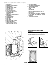
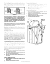
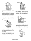
In order to access the tabs and install the earthquake
straps it is necessary to remove the top, front and side
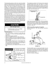
panels of the shroud as follows (see Figures 6 - 8):
Door opening
Unlock the door by rotating the lock counter-clockwise
with a wide, slot screwdriver.
Release the top and bottom door pins by prying the
pins out, using a small screwdriver.
Open the door (the door remains fastened to the left
side panel).
Remove the top casing (front).
Use a screwdriver to remove the six screws securing
the top casing.
Lift up and remove casing top (front).
1.
2.
3.
1.
2.
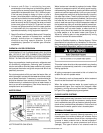
Remove the right side panel
Use a screwdriver to remove the screw from the
bottom, front of the right side panel.
Remove the three screws from the right side panel
towards the rear of the unit.
Remove the screw from the top of the unit.
Push the panel back and lift out.
Remove the left side panel
Use a screwdriver to remove the screw from the
bottom, front of the left side panel.
Remove the three screws from the left side panel
towards the rear of the unit.
Remove the screw from the top of the unit.
Push the panel back and lift out.
Access To
Door Pins
Door
Lock
Screws
Top Casing
(Front)
FIGURE 6
1.
2.
3.
4.
1.
2.
3.
4.