


26 www.americanwaterheater.com
SEQUENCE OF INSTALLATIONS
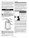
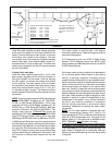
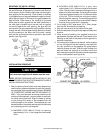
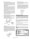
Cut a length of PVC pipe about 3.5 in. (9cm) longer than
the wall thickness at the opening. Glue the vent terminal
to this section of pipe. Slide the wall plate over the pipe to
stop against the vent terminal. Place a bead of caulking
(not supplied) around the gap between the pipe and cover
plate. Apply enough to fi ll some of the gap between the
pipe and wall. Place some of the caulking on the back
of the plate to hold it against the wall after installation. If
the vent pipe is installed up to the wall, with a coupling
on the end against the wall opening, the pipe with the
vent terminal can be prepared for gluing before inserting
through the wall. Slide the pipe through the wall and insert
into the coupling on the other side of the wall, making
sure that the vent terminal ends up pointed in the correct
position (see Figure 23).
FIGURE 23
INSTALLATION SEQUENCE
Vent terminals supplied with heater must be used.
CAUTION
NOTE: BEFORE BEGINNING INSTALLATION OF ANY
VENT PIPE READ THE VENT PIPE MANUFACTURER’S
INSTALLATION INSTRUCTIONS.
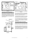
1. After the points of termination have been determined,
use the cover plates as templates to mark the holes for
the vent pipes to be inserted through the wall. BEWARE
OF CONCEALED WIRING AND PIPING INSIDE OF
WALL. If the vent terminals are being installed on the
outside of a fi nished wall, it may be easier to mark both
the inside and outside wall. Align the holes by drilling
a hole through the center of the template from the
inside through to the outside. The template can now
be positioned on the outside wall using the drilled holes
as a centering point for the template.
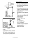
A. MASONRY SIDE WALLS Chisel an opening
approximately 1/2 in. (1.3cm) larger than the marked
circle.
B. WOODEN SIDE WALLS Drill a pilot hole
approximately 1/4 in. (0.64cm) outside of the marked
circle. This pilot hole is used as a starting point for a
saws-all or sabre saw blade. Cut around the marked
circle staying approximately 1/4 in (0.64cm) outside
of the line. (This will allow the vent pipe to easily
slide through the opening. The resulting gap will be
covered by the vent terminal cover plates.) Repeat
this step on the inside wall if necessary.
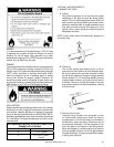
2. Cut a length of PVC pipe about 3.5 in. (9cm) longer
than the wall thickness at the opening.
3. Glue the vent terminal to the section of the pipe.
4. Slide the wall plate over pipe to stop against intake vent
terminal.
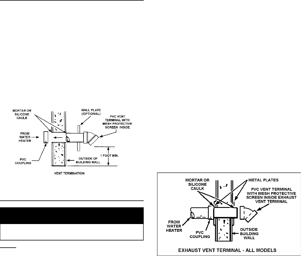
5. Place a bead of caulking (not supplied) around the
gap between the pipe and the wall. Place some of the
caulking on the back of the plate to hold it against the
wall after installation.
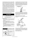
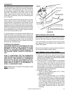
6. If the vent pipe is installed up to the wall, with a coupling
on the end against the wall opening, the pipe with
the vent terminal can be prepared for gluing before
inserting through the wall. Slide the pipe through the
wall and insert into coupling on the other side of the
wall, making sure that the vent terminal ends up pointed
in the correct position (see Figure 24).
FIGURE 24