


www.americanwaterheater.com 21
GAS PIPING
Make sure gas supplied is same type listed on model
rating plate. The inlet gas pressure must not exceed 14
in. WC (3.5 kPa) for natural and propane gas (L.P.). The
minimum inlet gas pressure shown on rating plate is that
which will permit fi ring at rated input.
All gas piping must comply with local codes and ordinances
or with the National Fuel Gas Code (ANSI Z223.1/ NFPA-
54). Copper or brass tubing and fi ttings (except tin lined
copper tubing) should not be used.
If the gas control valve is subjected to pressures exceeding
1/2 psi (3.5 kPa), the damage to the gas control valve could
result in a fi re or explosion from leaking gas.
If the main gas line shut-off serving all gas appliances is
used, also turn “off” the gas at each appliance. Leave all
gas appliances shut “off” until the water heater installation
is complete.
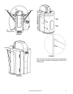
A gas line of suffi cient size must be run to the water
heater. The water heater is equiped with a 3/4 in. gas line
connection, however, for installations where a 1/2 in. gas
line will be used, a 90 degree reducing elbow is supplied
with every water heater.
Consult the current edition of National Fuel Gas Code
(ANSI Z223.1/NFPA 54) and your gas supplier concerning
pipe size.
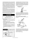
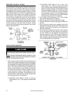
There must be:
• A readily accessible manual shut off valve in the gas
supply line serving the water heater, and
• A drip leg (sediment trap) ahead of the gas control valve
to help prevent dirt and foreign materials from entering
the gas control valve.
• A ground joint union or equivalent between the shut off
valve and control valve to permit servicing of the unit.
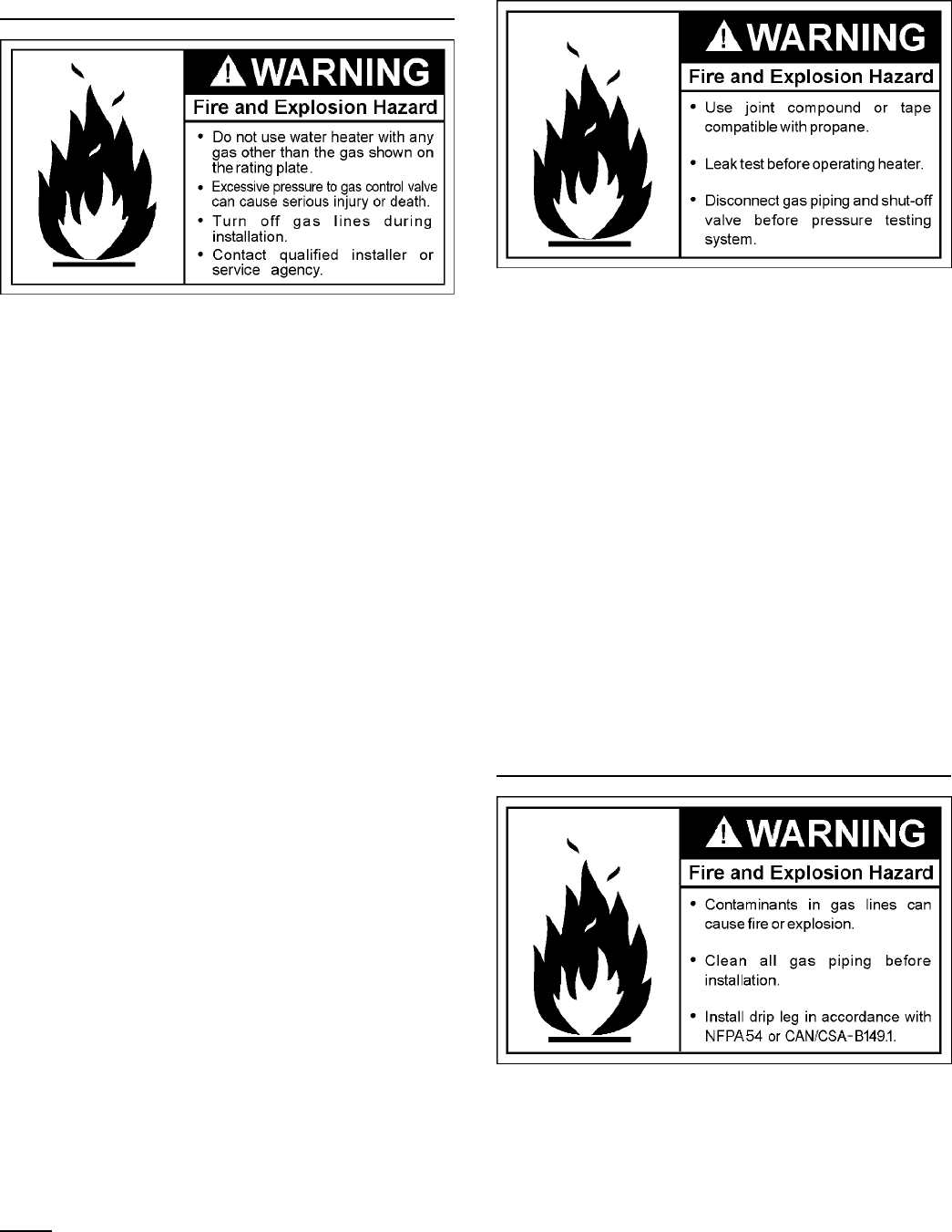
The appliance and its gas connections must be leak tested
before placing the appliance in operation. Use a leak test
solution, not a match or open fl ame.
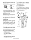
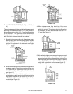
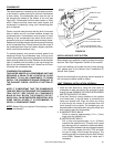
NOTE: An alternate location for the gas line entry is
possible. Drill a suitable hole centered on the crosshairs
on the left side panel.
Use pipe joint compound or Tefl on tape marked as being
resistant to the action of petroleum [Propane (L.P.)]
gases.
The appliance and its gas connection must be leak tested
before placing the appliance in operation.
The appliance and its individual shut-off valve must be
disconnected from the gas supply piping system during
any pressure testing of the system at test pressures in
excess of 1/2 psi (3.5 kPa).
It shall be isolated from the gas supply piping system
by closing its individual manual shut-off valve during
the pressure testing, the gas supply piping system at
test pressures equal to or less than 1/2 psi (3.5 kPa) is
considered isolated.
IMPORTANT: MAKE SURE THE GAS LINE IS PIPED WITH
HARD PIPE. AVOID FLEX LINE CONSTRUCTION FOR
GAS DUE TO POSSIBLE GAS FLOW PROBLEMS.
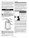
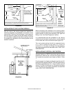
SEDIMENT TRAPS
A sediment trap shall be installed as close to the gas inlet
of the water heater as practical at the time of water heater
installation. The sediment trap shall be either a tee fi tting
with a capped nipple in the bottom outlet or other device
recognized as an effective sediment trap.
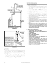
Contaminants in the gas lines may cause improper
operation of the gas control valve that may result in fi re
or explosion. Before attaching the gas line be sure that all
gas pipe is clean on the inside. To trap any dirt or foreign
material in the gas supply line, a drip leg (sometimes called