


www.americanwaterheater.com 25
CONDENSATE
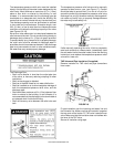
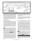
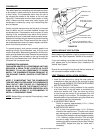
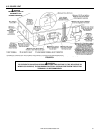
This water heater is a condensing unit and requires a drain
to be located in close proximity to allow the condensate
to drain safely. The condensate drains from the unit at
the exhaust tee located at the bottom of the unit (see
Figure 22). Condensate from this water heater is mildly
acidic. Please note that some local codes require that
condensate is treated by using a pH neutralizing fi lter
prior to disposal.
Caution must be used to ensure that the drain is free and
clear of debris and will not allow backfl ow through the
condensate tube. Consideration must be given to avoid
freezing of the condensate lines which could result in
excessive build up of condensate inside the water heater.
Waterproof heat tape may be required to prevent freezing
of the condensate lines. Please ensure that the outlet of
the condensate drain does not create a slippery condition
which could lead to personal injury.
To operate properly and prevent exhaust gases from
escaping through the condensate trap, the trap must
contain some water. Before being started for the fi rst time,
water must be added to the trap. Remove the condensate
tube (if installed) and add water to the trap through the
hole for the condensate tube until it fl ows from the hole.
(Re)install the condensate tube.
CONDENSATION WARNING:
THIS WATER HEATER IS A CONDENSING UNIT AND
REQUIRES A DRAIN TO BE LOCATED IN CLOSE
PROXIMITY TO ALLOW CONDENSATE TO DRAIN
SAFELY. THE CONDENSATE DRAINS FROM UNIT AT
THE EXHAUST ELBOW LOCATED AT BOTTOM OF
UNIT.
NOTE: IT IS IMPORTANT THAT THE CONDENSATE
TUBE NOT BE ELEVATED ABOVE THE CONDENSATE
TRAP OUTLET (SEE FIGURE 22). CONDENSATE
BUILD-UP WILL BLOCK THE EXHAUST OUTLET,
WHICH WILL CAUSE IMPROPER OPERATION. WITH
SOME INSTALLATIONS IT IS RECOMMEND TO
INSTALL A CONDENSATE PUMP.
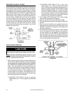
NOTE: Barbed fi tting not required if hard piping is used
to drain condensate.
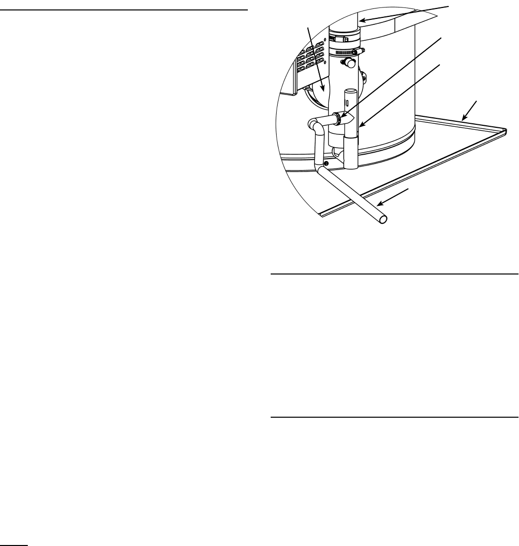
CONDENSATE TUBE -
SLOPE TO SUITABLE DRAIN
CONDENSATE
TRAP
VENTING
DRAIN PAN - ROUTE
TO SUITABLE DRAIN
EXHAUST
ELBOW
NOTE: THE CONDENSATE TUBE
MUST BE BELOW EXHAUST ELBOW.
BARBED FITTING
FIGURE 22
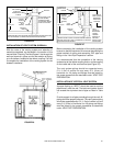
INSTALLATION OF VENT SYSTEM
Before beginning installation of piping system thoroughly
read the “Vent Pipe Preparation” section of this manual.
If you are installing your system so that it vents through
roof, please refer to the section titled “Installation Of
Vertical Vent System”.
Ensure the vent length is long enough that the outside air
will not cause the water heater to freeze.
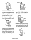
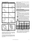
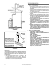
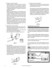
VENT TERMINAL INSTALLATION, SIDEWALL
1. Install the vent terminal by using the cover plate as
a template to mark the hole for the vent pipe to pass
through the wall. BEWARE OF CONCEALED WIRING
AND PIPING INSIDE THE WALL.
2. If the Vent Terminal is being installed on the outside
of a fi nished wall, it may be easier to mark both the
inside and outside wall. Align the holes by drilling
a hole through the center of the template from the
inside through to the outside. The template can now
be positioned on the outside wall using the drilled hole
as a centering point for the template.
3. A) MASONRY SIDE WALLS
Chisel an opening approximately 1/2 in. (1.3cm)
larger than the marked circle.
B) WOODEN SIDE WALLS
Drill a pilot hole approximately 1/4 in. (0.64cm)
outside of the marked circle. This pilot hole is used
as a starting point for a saws-all or sabre saw blade.
Cut around the marked circle staying approximately
1/4 in. (0.64cm) outside of the line. (This will allow
the vent to easily slide through the opening. The
resulting gap will be covered up by the Vent Terminal
cover plate.) Repeat this step on inside wall if
necessary.