


25
O
F
F
ON
M
P
C
1
3
2
WR
INLET
OUTLET
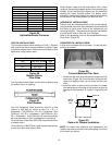
Main Regulator
Adjust
Inlet Pressure Tap
(Side of Valve)
Outlet Pressure Tap
(Side of Valve)
Main
Solenoid
Redundant
Solenoid
ON/Off
Switch
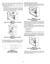
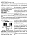
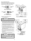
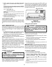
Figure 39
White Rodgers Model 36E22
CHECK GAS INPUT AND PRESSURES
Gas supply pressure and manifold pressure with the burn-
ers operating must be as specified on the rating plate.
CHECKING GAS PRESSURE
Gas inlet pressure should be checked and adjusted in
accordance to the type of fuel being consumed.
With Power and Gas Off:
1.
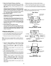
Honeywell Model VR8205, or White Rodgers Models
36E36 or 36E22, or Robertshaw Model 7222:
Connect
a water manometer or adequate gauge to the “inlet
pressure tap” of the gas valve.
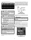
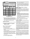
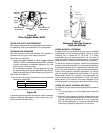
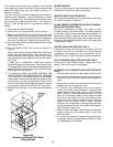
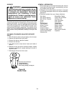
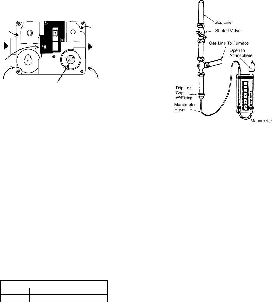
As an alternative method, inlet gas pressure can also
be measured by removing the cap from the drip leg and
installing a predrilled cap with a hose fitting (Figure 41).
With Power and Gas On:
2. Put furnace into heating cycle and turn on all other gas
consuming appliances.
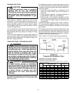
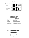
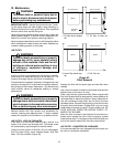
Inlet Gas Pressure
Natural Min. 5.0" W.C., Max. 10.0" W.C.
Propane Min. 11.0" W.C., Max. 14.0" W.C.
Inlet Gas Pressure Must Not Exceed the Maximum Value Shown.
Figure 40
If operating pressures differ from above, make necessary
pressure regulator adjustments, check piping size, etc.,
and/or consult with local utility.
Figure 41
Measuring Inlet Gas Pressure
(Alternate Method)
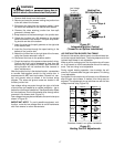
CHECK MANIFOLD PRESSURE
A tapped opening is provided in the gas valve to facilitate
measurement of the manifold pressure. See the “Outlet
Pressure Tap” in Figures 36, 37, 38, & 39. A “U Tube”
manometer having a scale range from 0 to 12 inches of
water should be used for this measurement. The manifold
pressure must be measured with the burners operating .
To adjust the pressure regulator, remove the adjustment
screw or cover on the gas valve. Turn out (counterclockwise)
to decrease pressure, turn in (clockwise) to increase pres-
sure. Only small variations in gas flow should be made by
means of the pressure regulator adjustment. For natural
gas, the manifold pressure must be between 3.2 and 3.8
inches water column (3.5 nominal). For propane gas, the
manifold pressure must be between 9.7 and 10.3 inches
water column (10.0 nominal). Any major changes in flow
should be made by changing the size of the burner orifice.
CHECK GAS INPUT (NATURAL GAS ONLY)
To measure the gas input using the gas meter proceed as
follows:
1. Turn off gas supply to all other appliances except the
furnace.
2. With the furnace operating, time the smallest dial on the
meter for one complete revolution. If this is a 2 cubic
foot dial, divide the seconds by 2; if it is a 1 cubic foot
dial, use the seconds as is. This gives the seconds per
cubic foot of gas being delivered to the furnace.