


12
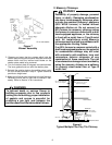
A B-vent installed as described in this section is considered
to be an enclosed vent system, and the sizing tables in
National Fuel Gas Code, NFPA 54/ANSI Z223.1 - latest
edition and in the National Standard of Canada, CAN/CGA
B149.1 and CAN/CGA B149.2 - latest editions and amend-
ments may be used.
If a flexible liner is to be used, it must be made of the proper
materials:
• For most residential applications, an aluminum liner
should be acceptable.
• If the combustion air supplied to the furnace will be
contaminated with compounds containing chlorine or
fluorine, a liner of AL294C stainless steel should be
used. Common sources of chlorine and fluorine com-
pounds include indoor swimming pools and chlorine
bleaches, paint strippers, adhesives, paints, varnishes,
sealers, waxes (which are not yet dried) and solvents
used during construction and remodeling. Various
commercial and industrial processes may also be
sources of chlorine/fluorine compounds.
• Heavier gauge 300 and 400 series stainless steel
liners were developed for use with oil or solid fuel
appliances. They are not suitable for use with gas-fired
appliances. Flexible liners specifically intended and
tested for gas applications are listed in the UL “Gas and
Oil Equipment Directory”. (UL Standard 1777).
For sizing of flexible liners, see Note 22 and the tables in
the National Fuel Gas Code, NFPA 54/ANSI Z223.1 -
latest edition and in the National Standard of Canada,
CAN/CGA B149.1 and CAN/CGA B149.2 - latest editions
and amendments.
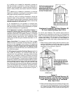
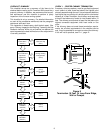
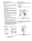
To install the liner, read and follow the liner manufacturer’s
instructions and your local codes. Excess liner length
should be pulled out of the chimney and cut off. Use caution
when doing this, as the cut edges of flexible liners may be
sharp. Do not spiral excess liner inside of the chimney.
Support the liner as recommended by the liner manufac-
turer.
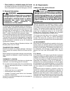
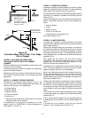
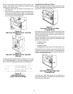
Some manufacturers of flexible liners offer an insulation
sleeve designed to be added to the liner before it is installed
in the chimney. (Poured insulation, either vermiculite or
other materials, is no longer recommended.) Insulation will
need to be added to the flexible liner if:
• It is required by the liner manufacturer’s instructions.
• The previous liner was properly sized and installed,
and suffered from condensation damage.
• It is required by your local building codes.
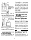
Even if none of those three conditions exist which require
additional liner insulation, the installer may wish to con-
sider it if:
• The local climate is very cold
• The chimney is very tall
• The vent connectors used are very long or have a large
number of elbows
• Local experience indicates that flexible liners installed
without insulation are likely to have condensation
problems.
Insulation must be selected and installed in accordance
with the liner manufacturer’s instructions.
Finally, cap the chimney and terminate the liner in accor-
dance with the liner manufacturer’s instructions.
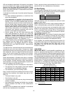
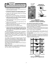
VI. Gas Piping
The rating plate is stamped with the model number, type of
gas and gas input rating. Make sure the furnace is equipped
to operate on the type of gas available.
Inlet Gas Pressure
Natural Min. 5.0" W.C., Max. 10.0" W.C.
Propane Min. 11.0" W.C., Max. 14.0" W.C.
Inlet gas pressure must not exceed the maximum value
shown in table above.
NOTE: Adjusting the minimum supply pressure below the
limits in the above table could lead to unreliable ignition.
Gas input to the burners must not exceed the rated input
shown on the rating plate. Overfiring of the furnace could
result in premature heat exchanger failure. Gas pressures
in excess of 14 inches water column could result in perma-
nent damage to the gas valve.
IMPORTANT NOTE: The furnace will naturally derate itself
with altitude. Do not attempt to increase the firing rate by
changing orifices or increasing the manifold pressure. This
can cause poor combustion and equipment failure.
At all altitudes, the manifold pressure must be within 0.3
inches WC of that listed on the “Specification Sheet” for the
fuel used. At all altitudes and with either fuel, the air
temperature rise must be within the range listed on the
furnace nameplate.
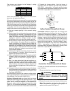
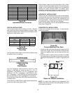
GAS PIPING
IMPORTANT NOTE: To avoid possible unsatisfactory op-
eration or equipment damage due to underfiring of equip-
ment, do not undersize the natural/propane gas piping from
the meter/tank to the furnace. Include all appliances which
may be operated simultaneously when sizing a trunk line.
The gas pipe supplying the furnace must be properly sized
based on gas flow required, specific gravity of the gas and
length of the run. The gas line installation must comply with
local codes, or in the absence of local codes, with the latest
edition of the National Fuel Gas Code ANSI Z223.1.
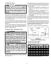
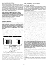
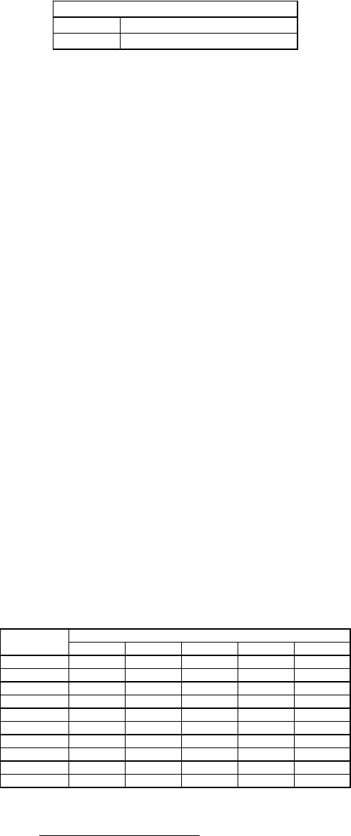
Natural Gas Capacity of Pipe
In Cubic Feet of Gas Per Hour (CFH)
Length of Nominal Black Pipe Size
Pipe in Feet 1/2" 3/4" 1" 1 1/4" 1 1/2"
10 132 278 520 1050 1600
20 92 190 350 730 1100
30 73 152 285 590 980
40 63 130 245 500 760
50 56 115 215 440 670
60 50 105 195 400 610
70 46 96 180 370 560
80 43 90 170 350 530
90 40 84 160 320 490
100 38 79 150 305 460
(Pressure 0.5 psig or less and pressure drop of 0.3" W.C.; Based on
0.60 Specific Gravity Gas)
CFH =
BTUH Furnace Input
Heating Value of Gas (BTU/Cubic Foot)