


21
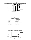
9. After a 15 second delay while flue products are purged
from the furnace heat exchanger, the induced draft
blower motor is de-energized.
10. The air circulation blower has an adjustable delay-off
timing of 60, 90, 120 or 180 seconds (starting from the
time the gas valve closes). This allows more heat from
the furnace to be transferred to the conditioned space.
After this time has elapsed, the blower will be de-
energized.
NORMAL COOLING SEQUENCE - INTEGRATED
IGNITION CONTROL
With the room thermostat in the FAN-AUTO position, the
indoor air circulation blower and outdoor condensing unit
will be energized when a call for cooling occurs. When the
call for cooling ends, the outdoor condensing unit will be de-
energized. The indoor air circulation blower will continue to
run for 45 seconds.
OTHER ITEMS
Constant Fan. During normal operation, the air circu-
lation blower will continually run at “Cooling” speed as
long as power is present at terminal G. If a call for heat
occurs, the blower will run at heating speed throughout
the heating cycle.
If a trip on high/auxiliary/rollout limit occurs, the air
circulation blower will run at “Heating” speed. Even if
power is present at terminal G, the blower will run at
heating speed until the limit closes.
X. Start-Up, Adjustments, and Checks
GENERAL OPERATION
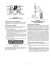
This furnace is equipped with an electronic ignition device
to light the burners and an induced draft blower to exhaust
combustion products.
An interlock switch prevents furnace operation if the blower
door is not in place. Keep the blower access doors in place
except for inspection and maintenance.
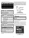
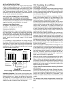
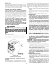
This furnace is also equipped with a self-diagnosing elec-
tronic control module. In the event a furnace component is
not operating properly, the control module LED will flash
on and off in a factory-programmed sequence, depending
on the problem encountered. This light can be viewed
through the observation window in the blower access door.
Refer to the
Diagnostic Signal Chart
for further explanation
of the lighting codes and Section X,
Abnormal Operation -
Integrated Ignition Control
for an explanation of the pos-
sible problem.
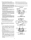
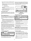
On new installations, or if a functional part such as the gas
valve, pressure switch, or limit control has been replaced,
verify that the furnace is operating properly after servicing.
Check furnace operation as outlined in the following in-
structions. If any sparking, odors, or unusual noises are
encountered, shut off electrical power and recheck for
wiring errors, or obstructions in or near the blower motors.
Various shipping materials must be removed before the
blower motor is operated.
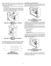
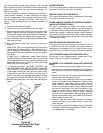
CAUTION
To prevent personal injury, use only blunt
pointed screws to attach the plenum to the
furnace and filter rack. Screws should not
be placed where they could interfere with
filter replacement.
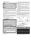
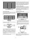
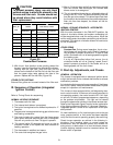
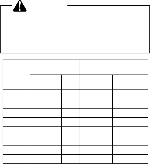
Size_Air
Dimension "A",
Inches
Minimum Recommended
Filter Sizes, Inches
Flow
Throwaway
Perm.
Fiberglass
Throwaway
Permanent
045_30 15-1/2 8 (2) 16x20x1 (2) 10x20x1
070_30 15-1/2 8 (2) 16x20x1 (2) 10x20x1
070_40 19-3/4 8 (2) 20x20x1 (2) 10x20x1
090_30 14-1/4 13 (2) 16x20x1 (2) 15x20x1
090_50 24-1/4 13 (2) 25x20x1 (2) 15x20x1
115_40 17-3/4 11 (2) 20x20x1 (2) 15x20x1
115_50 23-1/2 11 (2) 25x20x1 (2) 15x20x1
140_50 23-1/2 11 (2) 25x20x1 (2) 15x20x1
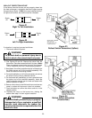
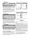
Figure 30
Counterflow Furnaces
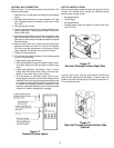
3. With the air flow direction arrow pointing toward the
furnace, insert the filters from the left side of the blower.
Starting with the right filter, push the filter into the
plenum so the bottom of the filter fits into the filter rack
and the upper edge rests against the side of the
plenum. Repeat with the left filter (Figure 29).
OTHER FILTER OPTIONS
External filter grilles can be used instead of the filter rack.
IX. Sequence of Operation (Integrated
Ignition Control)
Refer to Timing Charts for sequencing.
NORMAL HEATING SEQUENCE
1. Thermostat calls for heat.
2. The induced draft blower is energized.
3. The ignitor is energized and is allowed to preheat for 17
seconds.
4. The gas valve is energized delivering gas to the burners
and starting combustion.
5. The control checks for a signal from the flame sensor
within seven seconds after the gas valve is energized.
Gas will only continue to flow if a signal is present.
6. The control waits 30 seconds and turns on the air
circulation blower to the speed that was selected for
heating operation.
7. The thermostat is satisfied and opens.
8. The control de-energizes the gas valve.