


15
CHECKING GAS PIPING
CAUTION
To prevent personal injury or property
damage due to fire, the following
instructions must be performed regarding
gas connections, pressure testing, location
of shutoff valve and installation of gas
piping.
Before placing in operation, leak test the unit and gas
connections. To avoid the possibility of explosion or fire,
never use a match or open flame to test for leaks. Never
exceed specified pressures for testing. Higher pressure
may damage the gas valve and cause overfiring, resulting
in heat exchanger failure.
This unit and shutoff valve must be disconnected from the
gas supply piping system before supply piping system
pressure testing with test pressures in excess of 1/2 psig
(3.48 kPa).
This unit must be isolated from the gas supply system by
closing its manual shutoff valve before pressure testing of
gas supply piping system with test pressures equal to or
less than 1/2 psig (3.48 kPa).
TANKS AND PIPING - PROPANE GAS UNITS
WARNING
To prevent death, personal injury or property
damage due to fire or explosion caused by
a propane gas leak, install a gas detecting
warning device. Since rust can reduce the
level of odorant in propane gas, a gas
detecting warning device is the only reliable
way to detect a propane gas leak. Contact a
local propane gas supplier about installing
a gas detecting warning device.
WARNING
All metal inserts, screens or turbulators
must be removed from the heat exchanger
tubes when using propane gas. Failure to
comply could cause serious personal injury
or death. Failure to comply with this
requirement will also void warranty
coverage.
All propane gas equipment must conform to the safety
standards of the National Board of Fire Underwriters (See
NBFU Manual 58).
For satisfactory operation, propane gas pressure must be
10 inch WC at the furnace manifold with all gas appliances
in operation. Maintaining proper gas pressure depends on
three main factors:
1. Vaporization rate, depending on temperature of the
liquid, and “wetted surface” area of the container or
containers.
2. Proper pressure regulation. (Two-stage regulation is
recommended for both cost and efficiency).
3. Pressure drop in lines between regulators, and be-
tween second stage regulator and the appliance. Pipe
size will depend on length of pipe run and total load of
all appliances.
Complete information regarding tank sizing for vaporiza-
tion, recommended regulator settings, and pipe sizing is
available from most regulator manufacturers and propane
gas suppliers.
Since propane gas will quickly dissolve white lead or most
standard commercial compounds, special pipe dope must
be used. Shellac base compounds resistant to the actions
of liquefied petroleum gases such as Gasolac, Stalactic,
Clyde’s or John Crane are satisfactory.
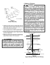
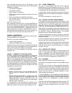
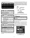
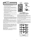
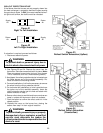
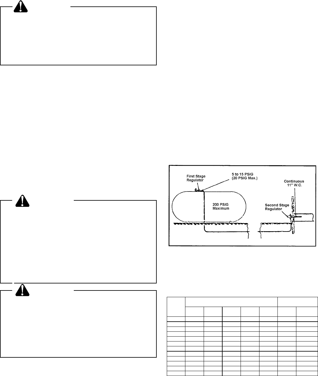
Refer to Figure 19 for typical propane gas installations.
Figure 19
Propane Gas Installation (Typ.)
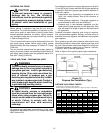
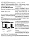
PROPANE GAS PIPING CHARTS
Sizing Between First and Second Stage Regulator
Maximum Propane Capacities listed are based on 2 psig pressure drop at 10 psig setting.
Capacities in 1,000 BTU/hour.
Pipe or Nominal Pipe Size
Tubing Tubing Size, O.D. Type L Schedule 40
Length, 3/8" 1/2" 5/8" 3/4" 7/8" 1/2" 3/4"
Feet
10 730 1,700 3,200 5,300 8,300 3,200 7,500
20 500 1,100 2,200 3,700 5,800 2,200 4,200
30 400 920 2,000 2,900 4,700 1,800 4,000
40 370 850 1,700 2,700 4,100 1,600 3,700
50 330 770 1,500 2,400 3,700 1,500 3,400
60 300 700 1,300 2,200 3,300 1,300 3,100
80 260 610 1,200 1,900 2,900 1,200 2,600
100 220 540 1,000 1,700 2,600 1,000 2,300
125 200 490 900 1,400 2,300 900 2,100
150 190 430 830 1,300 2,100 830 1,900
175 170 400 780 1,200 1,900 770 1,700
200 160 380 730 1,100 1,800 720 1,500
To convert to capacities at 15 psig settings - multiply by 1.130
To convert to capacities at 5 psig settings - multiply by 0.879